

Auto parts cleaning device
An auto parts and cleaning device technology, applied in the field of auto parts, can solve the problems of high cleaning cost, laborious and laborious, poor cleaning effect, etc., and achieve the effects of novel structure design, improved cleaning strength and high degree of automation
- Summary
- Abstract
- Description
- Claims
- Application Information
AI Technical Summary
Problems solved by technology
Method used
Image

Examples
Embodiment 1
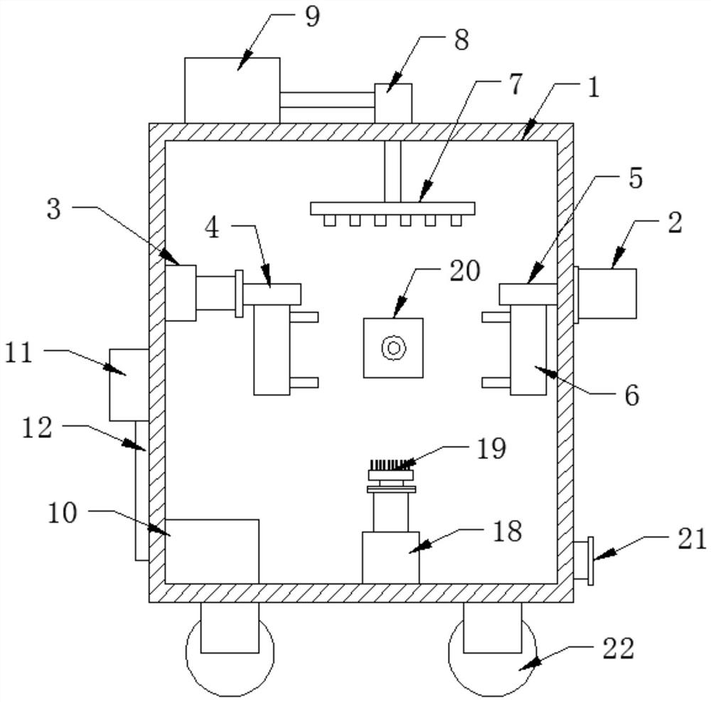
[0030] see Figure 1-3 , the present invention provides a technical solution: a cleaning device for auto parts, including a box body 1, a rotating motor 2 is installed on one side wall of the box body 1, and a telescopic Cylinder one 3, the output end of rotary motor 2 is connected with connecting rod two 5 located in the box body 1, the telescoping end of telescopic cylinder one 3 is connected with connecting rod one 4, and the bottoms of connecting rod one 4 and connecting rod two 5 are all installed There are mechanical claws 6, the first connecting rod 4 and the second connecting rod 5 are located on the same level, and the mechanical claws 6 installed on the first connecting rod 4 and the second connecting rod 5 can clamp the auto parts horizontally without tilting. Avoid disengagement during operation. The bottom of the side wall of the box body 1 is provided with a sewage outlet 21 through which the water source in the box body 1 can be replaced. The four corners of t...
Embodiment 2
[0033] Based on the content of embodiment 1, the present invention provides another kind of technical scheme:
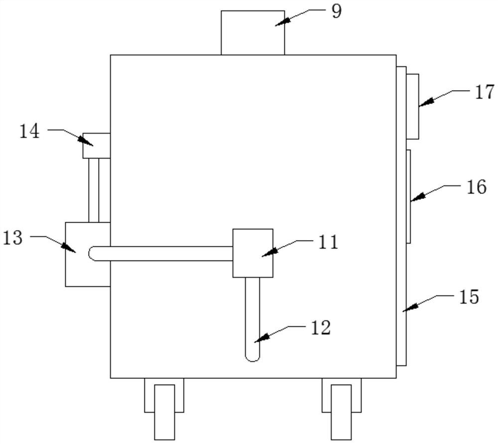
[0034] A filter box 10 is installed at the bottom of the inner cavity of the box body 1, and the filter box 10 is connected with the water tank 13 through a circulation pump 11 and a pipeline 12, and the liquid cleaned in the box body 1 can be filtered through the filter box 10, and the filtered The cleaner water source is delivered to the water tank 13 by the circulation pump 11, and the water is recycled to avoid waste of water source.
Embodiment 3
[0036] Based on the content of at least one of embodiment 1 and embodiment 2, the present invention provides another technical solution:
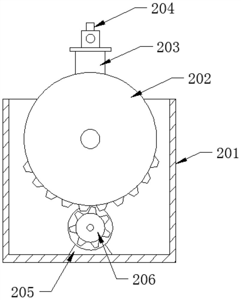
[0037] The high-pressure swing nozzle 20 includes a chassis 201 installed on the inner wall of the box body 1. A driven gear 202 and a driving gear 206 are arranged on the upper and lower sides of the inner cavity of the chassis 201 through rotating shafts, and a servo motor is installed inside the chassis 201. 205, the output end of the servo motor 205 is inserted into the center of the driving gear 206, and the side of the driven gear 202 extending out of the chassis 201 is fixedly connected with the high-pressure nozzle 204 through the fixed rod 203. During operation, the front and back of the servo motor 205 The rotation drives the driving gear 206 to rotate, and the driving gear 206 drives the driven gear 202 with incomplete teeth to reciprocate within a certain angle, thereby driving the high-pressure nozzle 204 installed on the driven...
PUM
 Abstract
Description
Claims
Application Information