
Crane base provided with protective structure

A protection structure and crane technology, applied in cranes, transportation and packaging, etc., can solve the problems of fixed structure, affecting the progress of the operation, and not being solved, and achieve the effect of reducing the degree of strain damage, improving the operation performance, and reducing the instability of the bottom.

Inactive Publication Date: 2020-09-25
但洁
View PDF1 Cites 0 Cited by
  • Summary
  • Abstract
  • Description
  • Claims
  • Application Information

AI Technical Summary

Problems solved by technology

[0005] Although the existing patent (notification number: CN109027537A) discloses a crane base with a protective structure, including the crane base, the top inside the crane base is equipped with a crane chassis, and the inside of the crane base at the bottom of the crane base is installed with Horizontal plate, but in the process of realizing the present invention, the inventor finds that at least the following problems in the prior art have not been solved;
[0006] The following defects still exist: 1. The overall structure is relatively fixed, and it is impossible to fine-tune the crane during operation, which leads to frequent and repeated adjustments of the crane before operation, which obviously reduces the practical effect of the base; 2. At the same time, it is impossible to quickly adjust the operation orientation according to the actual situation in a special environment, resulting in more limitations of the crane during operation, which not only affects the operation progress, but also brings more inconvenience to the operation of the staff; 3, and The protection performance of the base to the bottom of the crane is relatively weak, which leads to the decline of the working quality and stability of the crane in special environments and strong winds, and reduces the practical performance of the base, so it needs to be improved to solve the above problems

Method used


Image

  • Crane base provided with protective structure
  • Crane base provided with protective structure
  • Crane base provided with protective structure

Examples


Embodiment Construction

[0029] The following will clearly and completely describe the technical solutions in the embodiments of the present invention with reference to the accompanying drawings in the embodiments of the present invention. Obviously, the described embodiments are only some, not all, embodiments of the present invention. Based on the embodiments of the present invention, all other embodiments obtained by persons of ordinary skill in the art without making creative efforts belong to the protection scope of the present invention.

[0030] In the description of the present invention, it should be noted that the terms "upper", "lower", "inner", "outer", "front end", "rear end", "both ends", "one end", "another end" The orientation or positional relationship indicated by etc. is based on the orientation or positional relationship shown in the drawings, and is only for the convenience of describing the present invention and simplifying the description, rather than indicating or implying that ...


PUM


Abstract

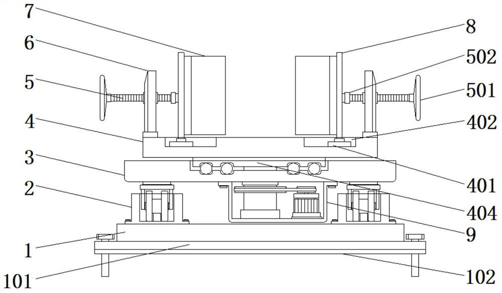
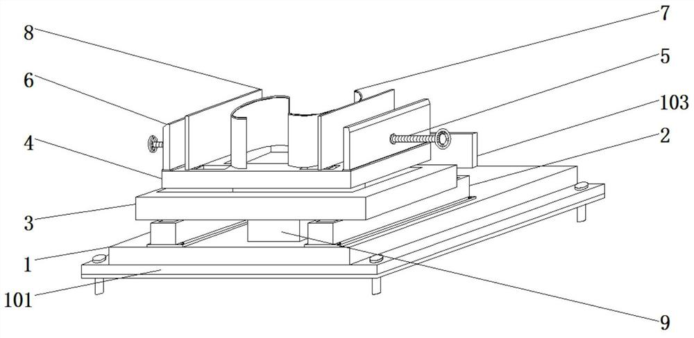
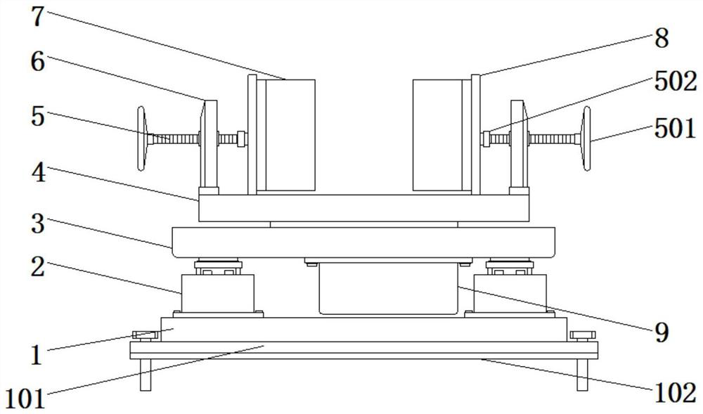
The invention discloses a crane base provided with a protective structure. The crane base comprises a base, a first mounting plate body and a second mounting plate body, and is characterized in that amounting cavity body is fixedly mounted at top of the base, rollers are arranged in the mounting cavity body in a rolling manner and fixedly mounted with the first mounting plate body through a mounting rack, the second mounting plate body is rotationally mounted at the top of the first mounting plate body, a mounting cover body is fixedly mounted at the bottom of the first mounting plate body, and a guide shaft connected with the second mounting plate body is rotationally mounted in the mounting cover body. According to the crane base provided with the protective structure, by means of an electric motor, the base can be effectively rotationally adjusted according to operation demands of a crane through the guide shaft and the first mounting plate body, by means of hydraulic telescopic rods, the crane can carry out pushing translation adjustment according to actual demands during working, and the base can perform effective protective work on the crane by the aid of arc protective suites, threaded rods and mounting plates.

Description

technical field [0001] The invention relates to the technical field of cranes, in particular to a crane base with a protective structure. Background technique [0002] A crane refers to a multi-action hoisting machine that vertically lifts and horizontally transports heavy objects within a certain range, also known as cranes, aerial cranes, and cranes; [0003] The main features of the tire crane are: the driving cab and the lifting control room are combined into one, which is evolved from a crawler crane (crawler crane). The shortcomings of crawler cranes (crawler cranes) that crawler shoes can cause damage to the road surface are material handling machinery; [0004] The bridge crane is a lifting device that is placed horizontally over the workshop, warehouse and stockyard for material lifting. Because its two ends are located on tall cement columns or metal supports, it is shaped like a bridge. The bridge frame of the bridge crane is laid along the The tracks on the ele...

Claims


Application Information

Patent Timeline
Patent Type & Authority Applications(China)
IPC IPC(8): B66C23/78B66C23/88
CPCB66C23/78B66C23/88B66C2700/0378
Inventor 但洁
Owner 但洁
Learn More