
Automatic correction method and system for aiming point of sniper rifle

An automatic correction and aiming point technology, applied in the field of light weapon shooting, can solve the problems of incorrect adjustment of the corrective sight, incorrect calculation of ballistic trajectory, and lack of other problems, so as to reduce errors and time, improve the degree of intelligence, and improve the reliability.

Active Publication Date: 2022-05-06
ARMOR ACADEMY OF CHINESE PEOPLES LIBERATION ARMY +1
View PDF12 Cites 0 Cited by
  • Summary
  • Abstract
  • Description
  • Claims
  • Application Information

AI Technical Summary

Problems solved by technology

[0004] Shooting accuracy and adaptability to the battlefield environment are important indicators for the design and research of sniper rifles. There are three deficiencies in the current manual calibration of sniper rifles: First, when the external environmental factors are complex, the sniper may not judge the environmental factors properly. Accurate, resulting in incorrect calculation of the ballistic trajectory; second, due to psychological stress or other factors, adjustment errors when correcting the height of the scope and the left and right knobs; third, the initial position cannot be found after adjusting the scope knob many times, resulting in errors in all subsequent corrections
[0005] Therefore, so far, there is a lack of effective methods and systems to automatically analyze environmental factors and automatically correct the aiming point, thereby improving the shooting accuracy of the sniper rifle and the adaptability to the war environment

Method used


Image

  • Automatic correction method and system for aiming point of sniper rifle
  • Automatic correction method and system for aiming point of sniper rifle
  • Automatic correction method and system for aiming point of sniper rifle

Examples


Embodiment 1

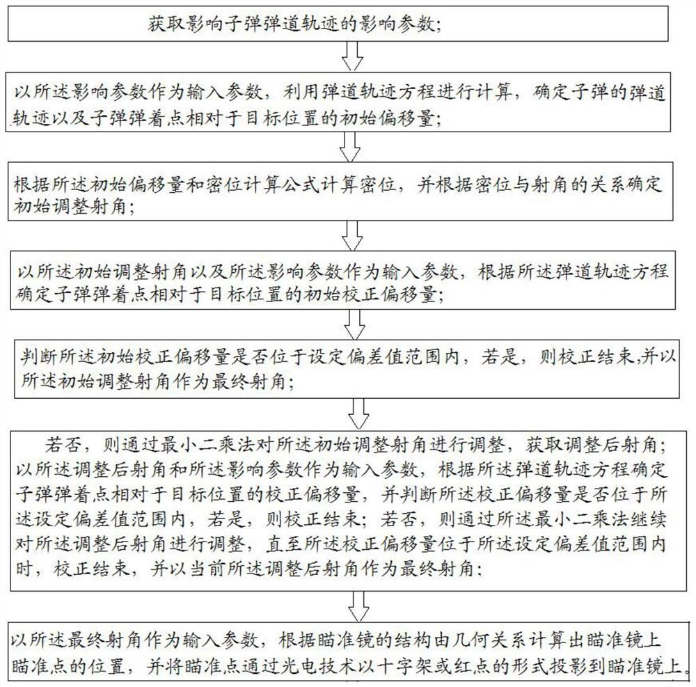
[0037] This embodiment is used to provide a kind of sniper rifle aiming point automatic correction method, such as figure 1 shown, including the following steps:

[0038] Step 1: Acquiring the influencing parameters affecting the ballistic trajectory of the bullet; the influencing parameters include wind speed, wind direction, ambient temperature, air humidity, atmospheric pressure, vertical angle, horizontal angle and distance of the target;

[0039] Specifically, the influencing parameters are obtained through a detection module installed on the body of the scope or the sniper rifle. The detection module includes a wind speed and direction measuring instrument, a laser distance measuring instrument, an angle measuring instrument, a temperature detector, an air humidity measuring instrument, and an air pressure measuring instrument. The wind speed and direction measuring instrument is used to measure wind speed and wind direction, the laser range finder is used to measure the ...

Embodiment 2

[0122] This embodiment is used to provide an automatic correction system for a sniper rifle aiming point, which uses the automatic correction method for a sniper rifle aiming point in Embodiment 1 to work, including a detection module, a ballistic calculation module and an automatic correction module;

[0123] The detection module is used to obtain the impact parameters that affect the ballistic trajectory of the bullet; the impact parameters include wind speed, wind direction, ambient temperature, air humidity, atmospheric pressure, vertical angle, horizontal angle and distance of the target;

[0124] The detection module is integrated and installed on the scope or sniper rifle; the detection module includes an anemometer, a laser rangefinder, an angle measuring instrument, a temperature detector, an air humidity measuring instrument, and an air pressure measuring instrument; The wind speed and direction measuring instrument is used to measure wind speed and wind direction; th...


PUM


Abstract

The invention relates to a method and system for automatically correcting the aiming point of a sniper rifle. The ballistic trajectory equation is obtained by analyzing the force of the bullet in the air, and the initial offset of the bullet is calculated through the ballistic trajectory equation, and the initial offset is used as an input parameter. Reversely calculate the initial adjustment firing angle of the gun, and further calculate the coordinates of the impact point of the initial adjustment firing angle under the shooting distance, and compare it with the target position to obtain the initial offset. If the initial offset is not within the set deviation value range When the angle of fire is within the range of the set deviation value, the angle of fire is adjusted by the least square method until the correction offset corresponding to the angle of fire after adjustment is within the range of the set deviation value, the final angle of fire is determined, and the corrected aiming point is directly projected on the sight , so that the method and system can be used to quickly realize the precise calibration of the aiming point, and the calibration speed is much faster than the manual calibration speed, and it can also adapt to a variety of complex environments, which provides a direction for the research of a new generation of sniper rifle aiming equipment.

Description

technical field [0001] The invention belongs to the technical field of light weapon shooting, and in particular relates to a method and a system for automatically correcting an aiming point when a sniper rifle shoots a fixed target. Background technique [0002] The trajectory of a sniper rifle bullet has a set of ballistic trajectory calculation equations. The trajectory is affected by many factors such as air temperature, air pressure, wind direction, wind speed, air humidity, shooting angle, bullet speed, and gravity. The trajectory is an offset arc. . The sniper rifles configured by the military of various countries are equipped with ballistic tables, which are the main reference for snipers when shooting long-distance targets. [0003] Snipers need to use aiming equipment when shooting long-distance targets. When shooting, the shooter needs to fully consider the influence of external factors and target distance on the trajectory, and correct the aiming point based on h...

Claims


Application Information

Patent Timeline
Patent Type & Authority Patents(China)
IPC IPC(8): F41G1/48F41G1/14F41G1/473F41G1/16
CPCF41G1/48F41G1/14F41G1/473F41G1/16
Inventor 鄢砚军彭志召童睆徐慧慧黄一斌
Owner ARMOR ACADEMY OF CHINESE PEOPLES LIBERATION ARMY
Learn More