An Adjustable Calibrated Refractive Compensation On-Column Fluorescence Detection Cell

A fluorescence detection and detection cell technology, applied in fluorescence/phosphorescence, measurement devices, material analysis by optical means, etc., can solve the problems of inability to take into account the sealing of the cell body, the disappearance of the refractive compensation effect, and the leakage of glycerin.

Active Publication Date: 2021-07-06
DALIAN INST OF CHEM PHYSICS CHINESE ACAD OF SCI
View PDF10 Cites 0 Cited by
  • Summary
  • Abstract
  • Description
  • Claims
  • Application Information

AI Technical Summary

Problems solved by technology

However, this structure cannot take into account the tightness of the cell body while being adjustable. After dripping glycerin, it can only maintain a limited refraction compensation time, such as 15 minutes. After the time exceeds, glycerin will slowly leak along the gap, making the refraction compensation effect gradually disappear.

Method used


Image

  • An Adjustable Calibrated Refractive Compensation On-Column Fluorescence Detection Cell
  • An Adjustable Calibrated Refractive Compensation On-Column Fluorescence Detection Cell
  • An Adjustable Calibrated Refractive Compensation On-Column Fluorescence Detection Cell

Examples


Embodiment 1

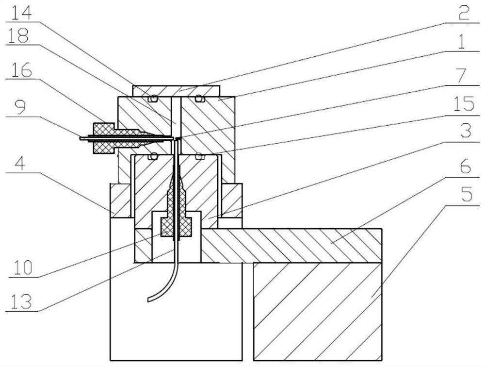
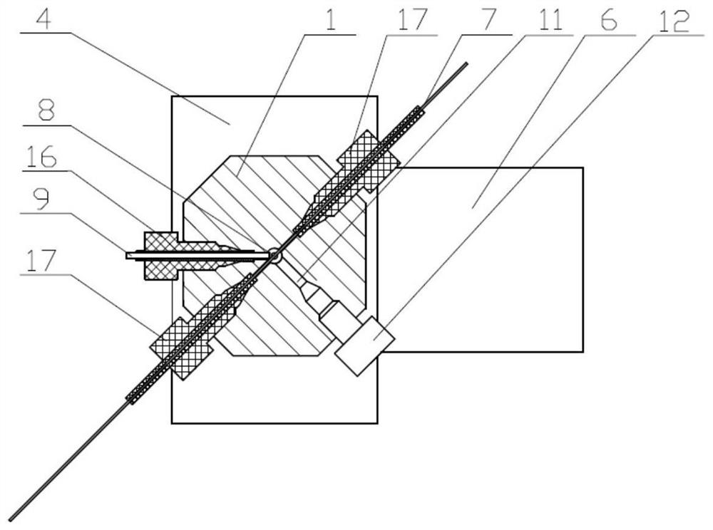
[0041] An adjustable calibration-refractive compensation laser-induced fluorescence detector, the excitation light source is a 450nm small semiconductor laser diode. The excitation fiber 13 and the excitation fiber ferrule structure 10 are coaxially placed in the ground groove of the pool base 1; the core diameter of the excitation fiber 13 is 50 μm, the numerical aperture is 0.22, and the distance between the excitation fiber 13 and the transparent light window 8 of the capillary is 50 μm; The inner diameter is 50 μm, the outer diameter is 365 μm, and the capillary 7 vertically passes through the center line of the cavity of the pool base 1; the collecting optical fiber 9 has a core diameter of 0.4 mm, a numerical aperture of 0.22, and an included angle of 45° with the capillary 7, and the center lines of the two are coplanar, One end of the collection fiber 9 is in physical contact with the transparent light window 8; the sockets of the capillary 7 and the collection fiber 9 ...

Embodiment 2

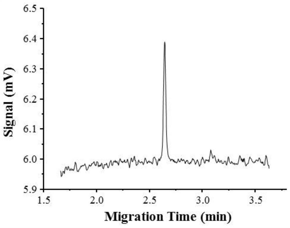
[0045] The fluorescence detection cell structure as described in Example 1, the excitation light source was replaced by a 470nm blue LED, and the detection sample was fluorescein isothiocyanate (FITC).

[0046] Experimental results: The calculated detection limit is 1.5×10 -10 M.


PUM

PropertyMeasurementUnit
diameteraaaaaaaaaa

Abstract

The invention provides an adjustable calibration—fluorescence detection cell on a refraction compensation column. Specifically, the adjustable components in the detection cell are mechanically connected to the three-dimensional displacement platform, and with the observation holes around the cell, the three-dimensional calibration of the excitation fiber-light window-collection fiber system can be performed on the micron scale; at the same time, the detection cell uses sealing rings, cards The sleeve and the plug are strictly sealed to ensure the long-term stability of the refractive compensation system after adding glycerin, and finally obtain a high detection sensitivity. The detection cell can be individually replaced with device parameters, such as the inner and outer diameters of the capillary, the inner and outer diameters of the excitation optical fiber and the collection optical fiber, so as to adapt to different application requirements.

Description

technical field [0001] The patent of the present invention relates to a fluorescence detection device, more specifically, to an adjustable calibration-fluorescence detection cell on a refraction compensation column. Background technique [0002] Fluorescence detection has extremely high sensitivity and plays an important role in ultratrace analysis. The detection cell is an important part of the detection system, and its performance determines the detection sensitivity. By designing and optimizing the structure of the detection cell, the stray light background of the excitation light of the system can be reduced, and the collection efficiency of fluorescence can be improved, so that a highly sensitive detection system can be obtained. [0003] At present, the on-column detection cell is the most widely used cell structure, which has the advantages of small extra-column effects and strong versatility. However, there is an obvious optical interface (quartz capillary n=1.467 / ...

Claims


Application Information

Patent Timeline
Patent Type & Authority Patents(China)
IPC IPC(8): G01N21/03G01N21/64
Inventor 耿旭辉关亚风宁海静高岩
Owner DALIAN INST OF CHEM PHYSICS CHINESE ACAD OF SCI
Why Eureka
Try Eureka