
Shifting register, driving method thereof, grid driving circuit and display device

A shift register and reset circuit technology, applied in the field of its drive method and gate drive circuit, shift register, and display device, can solve the problems of production efficiency affected by technological level standards, PU node leakage, poor display, etc.

Active Publication Date: 2020-09-25
FUZHOU BOE OPTOELECTRONICS TECH CO LTD +1
View PDF5 Cites 4 Cited by
  • Summary
  • Abstract
  • Description
  • Claims
  • Application Information

AI Technical Summary

Problems solved by technology

However, in the current frequency conversion product design, the design criterion of GOA is to ensure the high-frequency drive capability first, so the TFT Size needs to be designed very large. Such a large TFT will cause GOA due to the intensified leakage effect of the TFT after switching to the low-frequency display process. The internal PU node leaks electricity, which causes the GOA output waveform to be deformed and cause poor display. Therefore, current frequency conversion products are very prone to display failure during high-low frequency switching. For this problem, the current countermeasure is only to improve the leakage level of TFT through process control, but The improvement effect is often greatly reduced due to the inevitable fluctuation effect of the process level, and the stricter process level standard (Spec) will also seriously affect the actual production efficiency

Method used


Image

  • Shifting register, driving method thereof, grid driving circuit and display device
  • Shifting register, driving method thereof, grid driving circuit and display device
  • Shifting register, driving method thereof, grid driving circuit and display device

Examples


Embodiment Construction

[0067] In order to make the purpose, technical solutions and advantages of the embodiments of the present invention more clear, the following will clearly and completely describe the technical solutions of the embodiments of the present invention in conjunction with the drawings of the embodiments of the present invention. Apparently, the described embodiments are some, not all, embodiments of the present invention. Based on the described embodiments of the present invention, all other embodiments obtained by persons of ordinary skill in the art without creative efforts shall fall within the protection scope of the present invention.

[0068] Unless otherwise defined, the technical terms or scientific terms used herein shall have the usual meanings understood by those skilled in the art to which the present invention belongs. "First", "second" and similar words used in the description and claims of the present invention do not indicate any order, quantity or importance, but ar...


PUM


Abstract

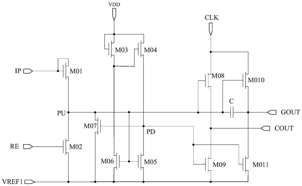
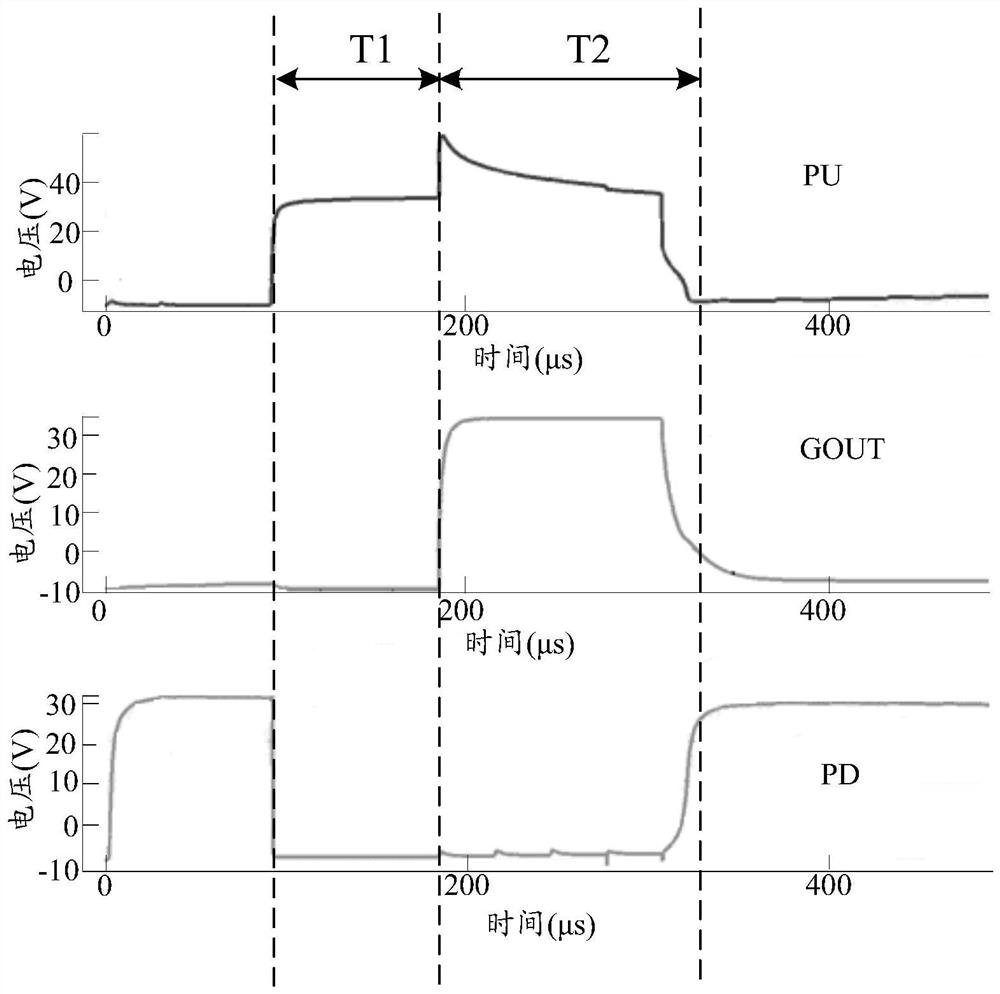
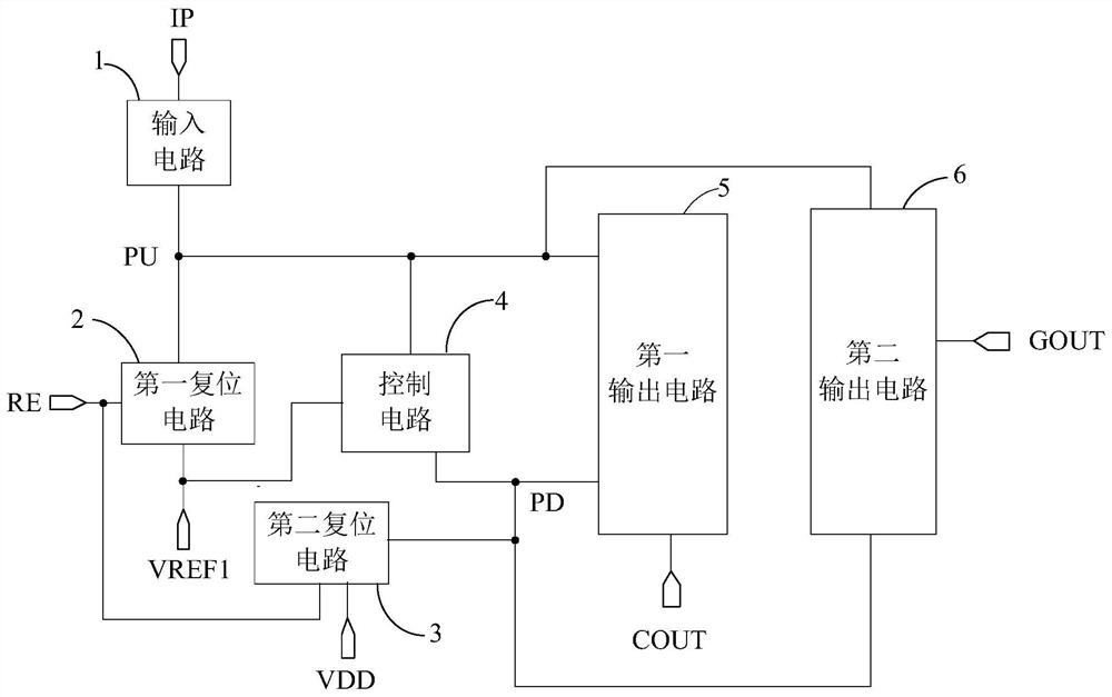
The invention discloses a shift register, a driving method thereof, a gate driving circuit and a display device, and the shift register comprises an input circuit which is used for responding to a signal of an input signal end and writing the signal of the input signal end into a pull-up node; a first reset circuit which is used for writing the signal of the first reference signal end into the pull-up node in response to the signal of the reset signal end; a second reset circuit which is used for writing the signal of the power supply end into the pull-down node in response to the signal of the reset signal end; a control circuit which is configured to respond to the signal written into the input signal end by the pull-up node and write the signal of the first reference signal end into thepull-down node, and write the signal of the first reference signal end into the pull-up node in response to the signal written into the power supply end by the pull-down node; a first output circuitwhich is used for enabling the cascade signal output end to output signals according to the signals of the pull-up node and the pull-down node; and a second output circuit which is used for enabling the driving signal output end to output signals according to the signals of the pull-up node and the pull-down node.

Description

technical field [0001] The invention relates to the field of display technology, in particular to a shift register, a driving method thereof, a gate driving circuit, and a display device. Background technique [0002] With the development of display technology, the requirements for displays are getting higher and higher. For the MNT of e-sports products, the refresh frequency can be switched from 48Hz to 165Hz through the Freesync function, and the driving voltage remains unchanged. In addition, there is also a frequency conversion requirement for ultra-large display screens in the market, and the refresh frequency span ranges from 30Hz to 240Hz; however, for the design of array substrate line drive (GOA) products, the design concepts of high frequency drive and low frequency drive are completely different. For high-frequency products, the extremely short charging time is the biggest constraint point, so the main design goal of high-frequency drive is to meet the drive capa...

Claims


Application Information

Patent Timeline
IPC IPC(8): G09G3/20G11C19/28
CPCG09G3/20G11C19/28G09G2310/0286
Inventor 胡波朴相镇林丽锋林琳琳方涛
Owner FUZHOU BOE OPTOELECTRONICS TECH CO LTD
Learn More