Sealing structure of electroplating mould

A sealing structure and mold technology, which is applied in the field of electroplating mold sealing structure, can solve the problems of large pressure area, inaccurate boss position, and easy breakage of milling cutter, etc., and achieve small sharp corner area, excellent sealing effect and excellent sealing effect Good results

Inactive Publication Date: 2014-07-23
深圳市长龙点金科技有限公司
View PDF5 Cites 0 Cited by
  • Summary
  • Abstract
  • Description
  • Claims
  • Application Information

AI Technical Summary

Problems solved by technology

[0004] 1. Low machining accuracy:
[0005] The groove of the rubber lower mold is located in the deepest part of the cavity, so the milling cutter must be very long. In addition, because the milling cutter is very long, its elasticity is also great, and it is easy to be skewed by the extrusion of the material side wall during processing, resulting in the position of the boss. Inaccurate
The position of the boss must be located at the edge of the plating area, so the extrusion with the side wall cannot be avoided
[0006] 2. Processing hours:
Since the milling cutter is thin and long, the processing speed must be very slow, otherwise the milling cutter is easy to break
This results in extended working hours
[0008] In addition, there will be solution accumulation at the right angle of the periphery of the boss. This position is not expected to be plated, and precious metals will also be plated. Because the fluidity of the solution at this position is not good, the brightness of the plating is dim
In order to solve this problem, it is usually processed on the periphery of the colloidal boss as attached image 3 The inclined surface shown, but this inclined surface needs to be scanned with a flat-end milling cutter circle by circle on the rubber mold. In order to make the scanning surface finer and smoother, the working hours can only be increased by ten times or even a hundred times.
[0009] 3. Poor sealing effect:
[0010] Since the use of a thinner milling cutter will further sacrifice the processing speed and accuracy, the milling cutter cannot be used thinner, so the width of the boss is wider, the pressure area is large, the pressure concentration is not good, and the sealing effect is poor

Method used


Image

  • Sealing structure of electroplating mould
  • Sealing structure of electroplating mould
  • Sealing structure of electroplating mould

Examples


Embodiment Construction

[0022] The present invention will be described in further detail below in conjunction with the accompanying drawings and specific embodiments.

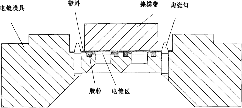
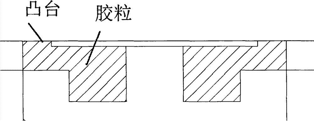
[0023] The electroplating mold sealing structure includes the electroplating mold body 1, the electroplating mold body is provided with an electroplating area 2, the edge of the electroplating area is provided with a groove 3, and the groove is embedded with rubber particles 4, and the cross-sectional shape of the groove is L-shaped. The cross-sectional shape of the colloidal particle is the same L-shape as the cross-sectional shape of the groove, and a boss 42 is provided at the bottom of the end of the horizontal section 41 of the colloidal particle section near the electroplating area, and the boss, the bottom of the horizontal section of the colloidal particle section and the upper surface of the groove There is a gap 43 between them, and the top of the horizontal section of the colloidal cross-section near the end of the electropl...


PUM


Abstract

The invention discloses a sealing structure of an electroplating mould. The sealing structure comprises an electroplating mould body, wherein an electroplating area is arranged on the electroplating mould body; a groove is formed in the edge of the electroplating area; colloidal particles are embedded in the groove; the cross section of the groove is in a shape of L; the cross section of each colloidal particle is in a shape of L, which is the same as the shape of the cross section of the groove; a boss is arranged on a transverse straight section, near the bottom at the tail end of the electroplating area, of the cross section of each colloidal particle; gaps are formed among the bosses, the bottoms of the transverse straight sections of the cross sections of the colloidal particles and the upper surface of the groove; the top of the transverse straight section, which is near the tail end of the electroplating area, of the cross section of each colloidal particle, is of a sharp corner higher than the upper surface of the electroplating mould. The sealing structure has the beneficial effects of being good in sealing effect and simple to machine.

Description

technical field [0001] The invention relates to an electroplating mold sealing structure. Background technique [0002] This technology is suitable for selective electroplating molds, applied to lead frames of electronic components (IC, diodes, LEDs, triodes, etc.), or connector terminals that are partially gold-plated, silver-plated, or tin-plated. The lead frame and terminals are made of metal (copper, iron or alloy) and are coiled in the form of strips. Selective electroplating is to control the position of the plating area through a special electroplating mold to ensure that the place that needs to be plated can be plated, and the place that does not need to be plated is not plated. Since the electroplating solution is easy to leak, install a silicone seal (commonly known as rubber particles) near the plating area, and press a silicone mask tape on the back of the lead frame or terminal to use the elasticity of the silicone to help seal the water flow. as attached fig...

Claims


Application Information

Patent Timeline
IPC IPC(8): C25D5/02
Inventor 曲悦峰
Owner 深圳市长龙点金科技有限公司
Why Eureka
Try Eureka