Access door

A channel door and channel technology, applied in the field of channel doors, can solve problems such as complex structure, inability to prevent air circulation, and space consumption

Pending Publication Date: 2020-09-29
TANGSHAN BAICHUAN IND SERVICES CO LTD
View PDF0 Cites 0 Cited by
  • Summary
  • Abstract
  • Description
  • Claims
  • Application Information

AI Technical Summary

Problems solved by technology

In some one-way doors, in order to meet the requirements of one-way traffic, the cross bars spaced apart from each other are arranged into a comb-shaped door leaf, and more than two (usually four) door leaves are installed on the shaft for one-way rotation, and then Use a row of fixed comb-toothed door leaves to intersect with the rotating door leaves to prevent reverse traffic, which cannot prevent air circulation, has no windproof function, and the passage width is large, and the useless passage (tha

Method used


Image

  • Access door
  • Access door
  • Access door

Examples


Embodiment 1

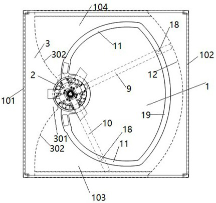
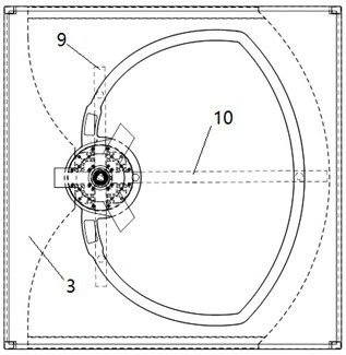
[0029] The passage door includes a passage 1 , and the passage 1 has a first side wall 101 , a second side wall 102 , an inlet 103 and an outlet 104 . The rotating shaft 2 is installed between the inlet 103 and the outlet 104, and has a blocking part 3 between it and the first side wall 101. The blocking part 3 includes a protrusion 301, and both sides of the protrusion 301 have concave arc surfaces 302, which is In order to prevent the door leaf from colliding with the blocking part during the rotation and translation process. The blocking portion 3 can also be a connecting plate that connects the rotating shaft 2 and the first side wall 101 and is perpendicular to the first side wall 101 .

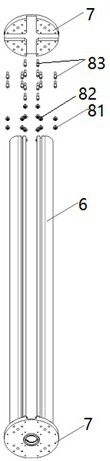
[0030] A cross-orthogonal first vertical slit 4 and a second vertical slit 5 are arranged on the rotating shaft 2 . The first vertical seam 4 and the second vertical seam 5 can be combined by four right-angle profiles or aluminum alloy profiles as the pillars 6. The upper and lower ends...

Embodiment 2

[0034] In this embodiment, the translational driving mode of the first door leaf 9 and the second door leaf 10 is changed, and there is no need to set guide rails on the channel and guide pieces on the door leaves, and the other conditions are the same as in Embodiment 1. In this example, the following methods are used to drive the translation of the door leaf:

[0035]The first gear 20 driven by the motor is set on the first vertical seam, and the first rack 21 is set on the first door leaf, the second gear 22 driven by the motor is set on the second vertical seam, and the second gear rack 21 is set on the second door leaf. The second rack 23 drives the first rack 21 through the first gear 20 to cause the translation of the first door leaf, and drives the second rack 23 through the second gear 22 to cause the translation of the second door leaf.

[0036] For the sake of aesthetics, the rack can be set on the top of the door leaf, and the rollers can be installed on the bottom...


PUM

PropertyMeasurementUnit
Radianaaaaaaaaaa

Abstract

The invention discloses an access door. The access door comprises a passageway. A rotating shaft, a first door leaf and a second door leaf are arranged on the passageway, and the first door leaf or the second door leaf rotates along with the rotating shaft and can horizontally move on the rotating shaft. When the first door leaf blocks the passageway, the first door leaf rotates along with the rotating shaft but does not horizontally move, and the second door leaf rotates along with the rotating shaft and can horizontally move. When the second door leaf blocks the passageway, the second door leaf rotates along with the rotating shaft but does not move horizontally, and the first door leaf rotates along with the rotating shaft and can move horizontally. The passageway is always blocked by the first door leaf or the second door leaf. The access door can always keep the passageway blocked during one-way or two-way passing, the number of door leaves is small, the needed passageway width issmall, the effective passageway proportion is high, the structure is simple and practical, and the windproof effect can be easily achieved.

Description

technical field [0001] The invention relates to a door, in particular to an access door arranged on an aisle to control passage. Background technique [0002] In places such as many stations, airports and other public places, access doors will be set on the access passages. Some doors only allow one-way traffic, and some doors allow two-way traffic. In some one-way doors, in order to meet the requirements of one-way traffic, the cross bars spaced apart from each other are arranged into a comb-shaped door leaf, and more than two (usually four) door leaves are installed on the shaft for one-way rotation, and then Use a row of fixed comb-toothed door leaves to intersect with the rotating door leaves to prevent reverse traffic, which cannot prevent air circulation, has no windproof function, and the passage width is large, and the useless passage (that is, the space occupied by the fixed door leaves) occupies High ratio requires more revolving door leaves and consumes a certain...

Claims


Application Information

Patent Timeline
IPC IPC(8): E06B3/90
CPCE06B3/90
Inventor 金强张天浩商月李炜孙红芳
Owner TANGSHAN BAICHUAN IND SERVICES CO LTD
Why Eureka
Try Eureka