
A self-purifying centrifugal fan for acid gas used in mine work

A centrifugal fan, acid gas technology, applied in the ventilation of mines/tunnels, components of pumping devices for elastic fluids, liquid fuel engines, etc., can solve problems that are difficult to deal with, and achieve extended service life and enhanced Protects and enhances the effect of absorbing effect

Active Publication Date: 2021-08-06
宜昌枫叶店子坪磷矿有限公司
View PDF6 Cites 0 Cited by
  • Summary
  • Abstract
  • Description
  • Claims
  • Application Information

AI Technical Summary

Problems solved by technology

[0005] The object of the present invention is to provide an acid gas self-purifying centrifugal ventilator for mine work that can automatically purify acid gas for the above-mentioned problem that the acid gas is easy to corrode the body but is difficult to be treated.

Method used


Image

  • A self-purifying centrifugal fan for acid gas used in mine work
  • A self-purifying centrifugal fan for acid gas used in mine work
  • A self-purifying centrifugal fan for acid gas used in mine work

Examples


Embodiment 1

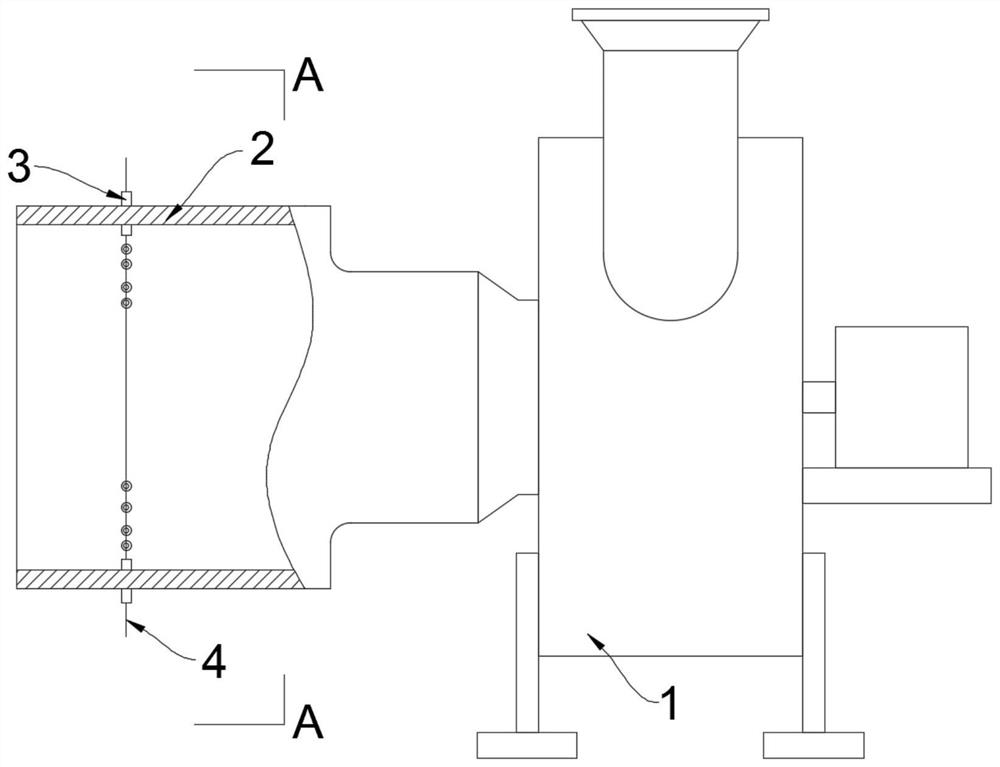
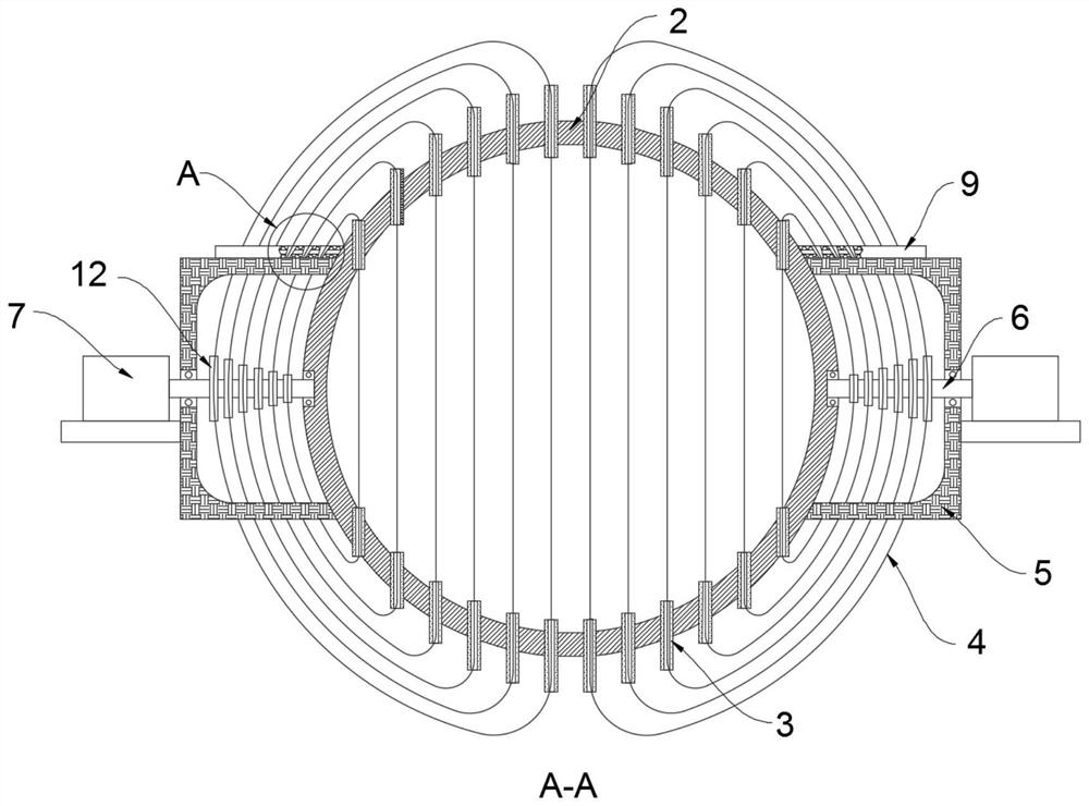
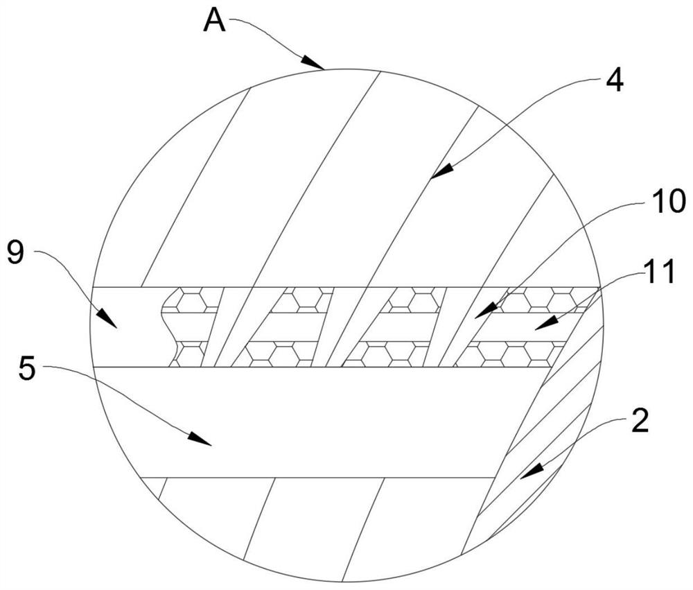
[0025] Such as Figure 1-3 As shown, an acid gas self-purifying centrifugal fan for mine work includes a main body 1 of the fan, and an air inlet pipe 2 is fixedly connected to the air inlet of the main body 1 of the fan, and the side wall of the air inlet pipe 2 is embedded with a A plurality of auxiliary cylinders 3, the two auxiliary cylinders 3 on the same vertical line are provided with a ring made of the same cotton thread 4, and the circumference of the ring made of cotton thread 4 increases sequentially from the inner ring to the outer ring, and the air intake Both left and right sides of the pipe 2 are provided with drive boxes 5, and the drive boxes 5 are fixedly connected to the outer wall of the air inlet pipe 2.

[0026] In this embodiment, the multiple cotton threads 4 on the same side all pass through the side wall of the drive box 5 and are driven by the drive mechanism in the drive box 5. The drive mechanism includes a rotating shaft 6, and one end of the rota...

Embodiment 2

[0032] Such as Figure 4-5 As shown, the difference between this embodiment and Embodiment 1 is that the air inlet pipe 2 includes two independent fixed pipes 21 and a rotating ring 22, and the rotating ring 22 is sealed and rotated with the outer walls of the two fixed pipes 21. Connection, specifically, the inner wall of the rotating ring 22 is fixedly connected with the connecting ring 14, the fixed pipe 21 is provided with an annular groove 15 matching the connecting ring 14, the connecting ring 14 and the annular groove 15 are connected in a sealed and rotating manner, and the auxiliary cylinder 3 1. The cotton thread 4 and the driving box 5 are both arranged on the outer wall of the rotating ring 22. It should be noted that the rotating ring 22 is provided with a plurality of air inlet holes 13 arranged obliquely.

[0033] In this embodiment, the setting of the rotating ring 22 is that the rotating ring 22 is rotatably sleeved on the outer wall of the fixed pipe 21. When...


PUM


Abstract

The invention belongs to the field of industrial equipment, and in particular relates to an acid gas self-purifying centrifugal fan for mine work, which includes a main body of the fan, an air inlet pipe is fixedly connected to the air inlet of the main body of the fan, and the side wall of the air inlet pipe runs through Embedded with multiple auxiliary cylinders, the two auxiliary cylinders on the same vertical line are provided with a ring made of the same cotton thread, and the left and right sides of the air inlet pipe are equipped with drive boxes, and the drive boxes are fixedly connected to the outside of the air inlet pipe The multiple cotton threads on the same side all run through the side wall of the drive box and are driven by the drive mechanism in the drive box. The drive mechanism includes a rotating shaft, one end of which is rotatably connected to the outer wall of the air inlet pipe, and is fixedly installed on the side wall of the drive box. The driving part is fixedly connected with the other end of the rotating shaft, the driving box is filled with alkaline solution, the side wall of the driving box is fixedly connected with a fixing plate, the fixing plate is provided with a tapered hole, and the cotton thread runs through the corresponding tapered hole. hole. The invention can efficiently and completely remove the acid gas in the air.

Description

technical field [0001] The invention belongs to the field of industrial equipment, in particular to an acid gas self-purifying centrifugal ventilator for mine work. Background technique [0002] Centrifugal fans are widely used in various fields, especially for the need to maintain air circulation in the workplace, the application of centrifugal fans is essential, such as mine construction and mineral excavation, etc. Ventilation means work safety. [0003] Then, because the air inside the general mine contains a large amount of acidic air, these acidic gases enter the fan through the fan inlet, collide with the fins inside the fan, the inner wall of the housing, etc., and adhere to the inside of the fan. The fixed structure of the ventilator causes a large amount of acid gas to accumulate but is difficult to remove, which will cause corrosion and damage to the internal structure of the ventilator, affect the working efficiency of the ventilator and greatly reduce the servic...

Claims


Application Information

Patent Timeline
Patent Type & Authority Patents(China)
IPC IPC(8): F04D17/16F04D29/46F04D29/70E21F1/00E21F17/00B01D53/40B01D53/78
CPCB01D53/40B01D53/78E21F1/00E21F17/00F04D17/16F04D29/462F04D29/703
Inventor 陈科宏夏坤
Owner 宜昌枫叶店子坪磷矿有限公司
Learn More