Fan control method, device and system

A fan control and working temperature technology, which is applied in pump control, engine control, non-variable pumps, etc., can solve problems such as equipment overheating and failure to work normally, control system failure, sensor damage, etc., to achieve rapid response to equipment load changes, Fan speed changes smoothly and reduces fan noise

Active Publication Date: 2020-09-29
XIAN NOVASTAR TECH
View PDF7 Cites 6 Cited by
  • Summary
  • Abstract
  • Description
  • Claims
  • Application Information

AI Technical Summary

Problems solved by technology

[0002] In the existing chassis heat dissipation technology solution, the fan speed control process is completely dependent on the collected ambient temperature. If the ambient temperature is not collected correctly or the sensor is damaged, the entire control system will fail, which may cause the device to overheat and fail to work normally or even be damaged.

Method used


Image

  • Fan control method, device and system
  • Fan control method, device and system
  • Fan control method, device and system

Examples


no. 1 example

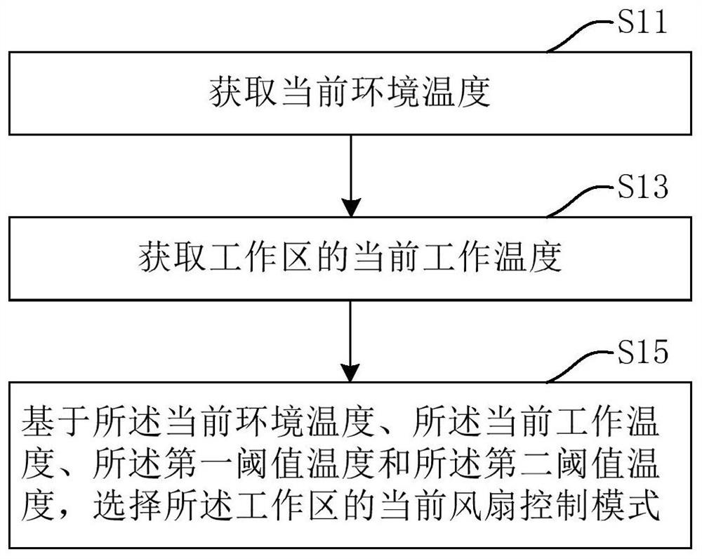
[0028] Such as Figure 1A As shown, a fan control method provided by the first embodiment of the present invention includes steps:

[0029] S11: Obtain the current ambient temperature;

[0030] S13: Obtain the current working temperature of the working area; and

[0031] S15: Based on the current ambient temperature, the current operating temperature, the first threshold temperature, and the second threshold temperature, select a current fan control mode in the working area.

[0032] Wherein, step S11 includes, for example, sub-steps: collecting a plurality of ambient temperatures within a certain period of time; filtering the plurality of ambient temperatures to obtain the average value of the ambient temperature; and averaging the ambient temperatures value as the current ambient temperature.

[0033] Step S13 includes, for example, sub-steps: collecting multiple operating temperatures of each of the multiple temperature measuring points in the working area within a certai...

no. 2 example

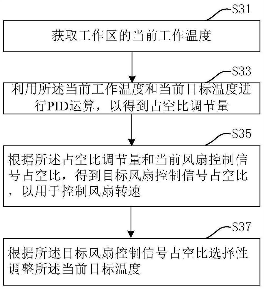
[0050] Such as Figure 2A As shown, a fan control method provided by the second embodiment of the present invention includes steps:

[0051] S31: Obtain the current working temperature of the working area;

[0052] S33: Using the current working temperature and the current target temperature to perform a PID calculation to obtain a duty cycle adjustment amount;

[0053] S35: Obtain a target fan control signal duty cycle according to the duty cycle adjustment amount and the current fan control signal duty cycle, so as to control the fan speed; and

[0054] S37: Selectively adjust the current target temperature according to the duty cycle of the target fan control signal.

[0055] Further, for step S37, as Figure 2B As shown, it may include sub-steps:

[0056] S371: Determine the relationship between the duty cycle of the target fan control signal, the upper and lower limits of the duty cycle of the fan control signal corresponding to the current target temperature, and the...

no. 3 example

[0067] see image 3 , a fan control device 30 proposed by the third embodiment of the present invention includes: a first acquisition module 31 , a second acquisition module 33 and a selection module 35 .

[0068] Wherein, the first obtaining module 31 is used to obtain the current ambient temperature, for example; the second obtaining module 33 is used, for example, to obtain the current working temperature of the work area; and the selection module 35 is used, for example, to obtain , the first threshold temperature and the second threshold temperature, selecting a current fan control mode in the working area to perform fan control. Wherein, the first threshold temperature is set based on the current ambient temperature, for example, and the second threshold temperature includes, for example, a preset maximum tolerable ambient temperature and a preset maximum tolerable working temperature.

[0069] As for the specific functional details of the first acquisition module 31 , ...


PUM


Abstract

The embodiment of the invention relates to a fan control method, device and system. The fan control method, for example, comprises the steps that current environment temperature is obtained; current working temperature of a working area is obtained; and based on the current environment temperature, the current working temperature, first threshold temperature and second threshold temperature, a current fan control mode of the working area is selected to carry out fan control. According to the embodiment, corresponding fan rotating speed control strategies can be selected according to the current working state of the working area so as to automatically match the heat dissipation requirements at different temperatures.

Description

technical field [0001] The invention relates to the technical field of heat dissipation and control, in particular to a fan control method, a case fan control device and a case fan control system. Background technique [0002] In the existing chassis heat dissipation technology solution, the fan speed control process completely depends on the collected ambient temperature. If the collected ambient temperature is inaccurate or the sensor is damaged, the entire control system will fail, which may cause the device to overheat and fail to work normally or even be damaged. Contents of the invention [0003] Therefore, in order to overcome the deficiencies of the prior art, embodiments of the present invention provide a fan control method, a fan control device, and a fan control system. [0004] On the one hand, a fan control method proposed by an embodiment of the present invention includes the steps of: acquiring a current ambient temperature; acquiring a current operating tem...

Claims


Application Information

Patent Timeline
Patent Type & Authority Applications(China)
IPC IPC(8): F04D27/00
CPCF04D27/004F05D2270/303F05D2270/313F05D2270/706
Inventor 王伙荣周晶晶夏玺钧
Owner XIAN NOVASTAR TECH
Why Eureka
Try Eureka