A support and fixing structure for water conservancy pipeline
A technology for fixing structures and pipelines. It is applied in the direction of pipeline supports, expansion compensation devices for pipelines, and pipe components. It can solve problems such as inconvenient adjustments, and achieve the effects of increasing service life, reducing accidents, and eliminating angle deviations.
- Summary
- Abstract
- Description
- Claims
- Application Information
AI Technical Summary
Problems solved by technology
Method used
Image
Examples
specific Embodiment 1
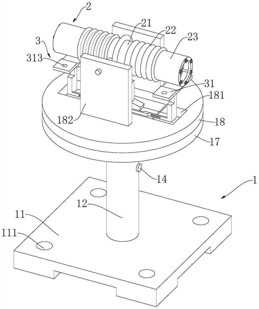
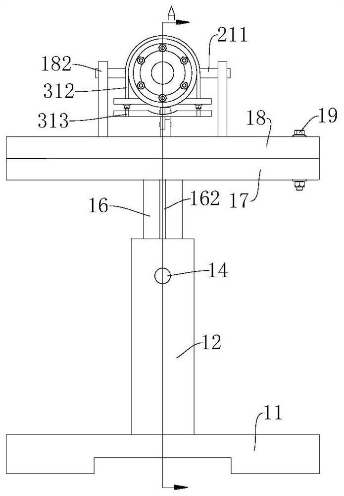
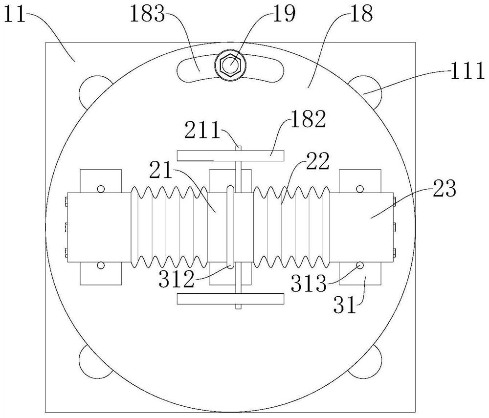
[0032] like Figure 1 to Figure 4 As shown, a support and fixing structure for water conservancy pipelines provided by an embodiment of the present invention includes a frame 1 and a connecting pipe 2, wherein:
[0033]Frame 1 comprises base 11, support column 12, worm gear 13, first knob 14, positioning key 15, slide bar 16, first supporting platform 17, second supporting platform 18 and first bolt 19, and base 11 is provided with several installations. The hole 111, the lower end of the support column 12 is fixedly connected to the base 11, the support column 12 is provided with a first chute 121 for accommodating the slide bar 16 along the vertical direction, the slide bar 16 is slidably connected to the first chute 121, the slide The rod 16 is provided with a rack 162 along the vertical direction, and the support column 12 is provided with a first receiving groove 123, and the worm wheel 13 is rotatably connected to the first receiving groove 123, and a gear 131 is coaxial...
specific Embodiment 2
[0038] In Example 1, since the common connecting pipe 2 cannot absorb the change in thermal installation and contraction after the pipe is installed, it is easy to cause a large stress between the water conservancy pipe and the connecting pipe 2, and it cannot adapt to water conservancy pipes of different specifications. In order to reduce the length of water conservancy pipelines affected by external factors, improve compatibility and practicality, so on the basis of embodiment 2, such as Figure 5 to Figure 7 As shown, the connecting pipe 2 in this embodiment includes an intermediate pipe 21, two flexible pipes 22 and two installation pipes 23, and the two ends of the intermediate pipe 21 are respectively fixedly connected to one end of the two flexible pipes 22, and the two flexible pipes 22 The other ends of the two mounting pipes 23 are respectively fixedly connected to one end, the rotating rod 211 is fixedly connected to the outer side wall of the middle pipe 21, and the...
specific Embodiment 3
[0044] In Embodiment 2, since the connecting pipe 2 is not fixed enough reliably, and in actual use, in order to ensure the structural stability, the support device is sometimes required to be rigid, in order to achieve more stable support, and in order to facilitate the opening of the connecting pipe 2 Or close the function of flexible pipe 22, so on the basis of embodiment 2, as Figure 5 As shown, the present embodiment also includes a support assembly 3, the support assembly 3 also includes a positioning plate 31, a connecting rod 32, a slider 34, a matching block 35 and a hinged rod 36, and the three positioning plates 31 are respectively located on the middle pipe 21 and the two Below the first installation pipe 23, a fitting groove corresponding to the outer diameter of the connecting pipe 2 is provided on the positioning plate 31, and two locking holes 311 are provided on the positioning plate 31, and a locking hoop 312 is provided in conjunction with the locking holes ...
PUM
 Abstract
Description
Claims
Application Information
 - R&D
- Intellectual Property
- Life Sciences
- Materials
- Tech Scout
- Unparalleled Data Quality
- Higher Quality Content
- 60% Fewer Hallucinations
Browse by: Latest US Patents, China's latest patents, Technical Efficacy Thesaurus, Application Domain, Technology Topic, Popular Technical Reports.
© 2025 PatSnap. All rights reserved.Legal|Privacy policy|Modern Slavery Act Transparency Statement|Sitemap|About US| Contact US: help@patsnap.com


