
Multi-chip testing device and method

A technology of test device and test method, which is applied in the direction of measuring device, electronic circuit test, measuring electricity, etc., can solve the problems of low test accuracy and low test efficiency, and achieve the effect of improving test efficiency and test accuracy.

Pending Publication Date: 2020-09-29
GLOBAL ENERGY INTERCONNECTION RES INST CO LTD +2
View PDF0 Cites 0 Cited by
  • Summary
  • Abstract
  • Description
  • Claims
  • Application Information

AI Technical Summary

Problems solved by technology

[0006] Therefore, the technical problem to be solved by the present invention is to overcome the defects of low test accuracy and low test efficiency in the prior art, thereby providing a multi-chip test device and test method

Method used


Image

  • Multi-chip testing device and method
  • Multi-chip testing device and method
  • Multi-chip testing device and method

Examples


Embodiment Construction

[0060] The technical solutions of the present invention will be clearly and completely described below in conjunction with the accompanying drawings. Apparently, the described embodiments are some of the embodiments of the present invention, but not all of them. Based on the embodiments of the present invention, all other embodiments obtained by persons of ordinary skill in the art without making creative efforts belong to the protection scope of the present invention.

[0061] In the description of the present invention, it should be noted that the terms "center", "upper", "lower", "left", "right", "vertical", "horizontal", "inner", "outer" etc. The indicated orientation or positional relationship is based on the orientation or positional relationship shown in the drawings, and is only for the convenience of describing the present invention and simplifying the description, rather than indicating or implying that the referred device or element must have a specific orientation, ...


PUM


Abstract

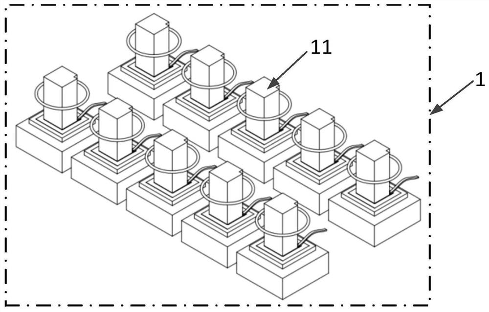
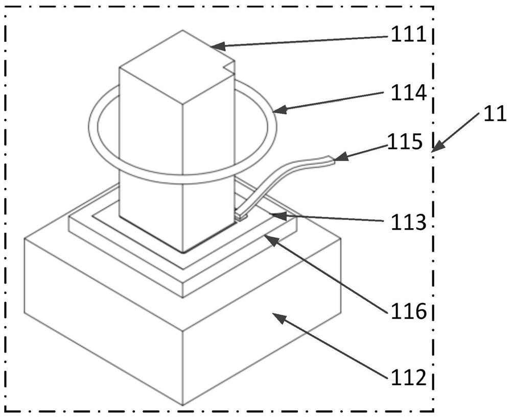
The invention discloses a multi-chip testing device and method. The device comprises: a plurality of testing subunits which are arranged in parallel, wherein each test subunit comprises a first test electrode and a second test electrode, the first test electrode and the second test electrode are suitable for being electrically connected with a to-be-tested semiconductor chip unit, and the first test electrode can provide pressure for the semiconductor chip unit; and a current collector suitable for obtaining test current passing through the first test electrode or the second test electrode. According to the multi-chip testing device, the testing precision and the testing efficiency can be improved.

Description

technical field [0001] The invention relates to the field of semiconductor device testing, in particular to a multi-chip testing device and testing method. Background technique [0002] At present, the test device used when testing the whole wafer or bare chip of the power semiconductor chip is usually a probe card. The probe card is used as a test interface to connect the electrical test instrument and the semiconductor chip. The parameters of the semiconductor chip are tested. During the testing process, the bottom of the semiconductor chip is positioned using a vacuum adsorption system, and the top of the semiconductor chip is directly in contact with the electrodes of the semiconductor chip through the probes in the probe card, and then cooperates with electrical testing instruments and software control to achieve automatic measurement. Purpose. The probe card simulates the welding of the bonding wire and the semiconductor chip in the package structure of the soldered ...

Claims


Application Information

Patent Timeline
Patent Type & Authority Applications(China)
IPC IPC(8): G01R31/28
CPCG01R31/2886G01R31/2891
Inventor 林仲康石浩张喆
Owner GLOBAL ENERGY INTERCONNECTION RES INST CO LTD
Learn More