Novel hydraulic bulging test clamp

A technology of hydraulic bulging and test fixtures, which is applied in the direction of measuring devices, instruments, scientific instruments, etc., can solve the problems of uneven sample clamping, inaccurate measurement, poor safety, etc., to reduce the time used, high measurement reliability, Even clamping effect

Pending Publication Date: 2018-06-19
CHINA SPECIAL EQUIP INSPECTION & RES INST
View PDF0 Cites 1 Cited by
  • Summary
  • Abstract
  • Description
  • Claims
  • Application Information

AI Technical Summary

Problems solved by technology

[0004] The purpose of the present invention is to provide a new type of hydraulic bulging test fixture to solve the problems of cumbersome installation, uneven sample clamping, inaccurate measurement and poor safety in the existing expansion test equipment

Method used


Image

  • Novel hydraulic bulging test clamp
  • Novel hydraulic bulging test clamp
  • Novel hydraulic bulging test clamp

Examples


Embodiment 1

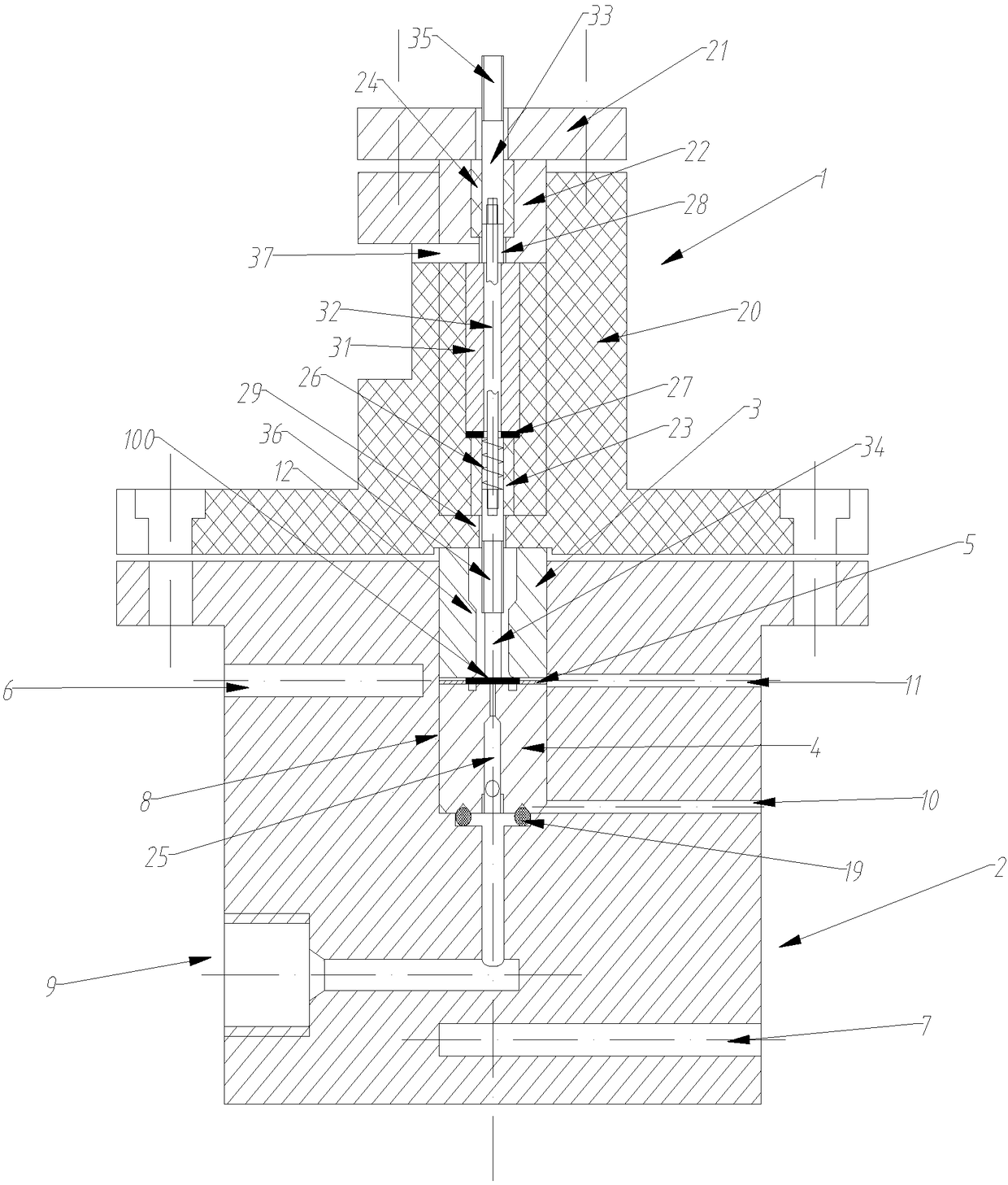
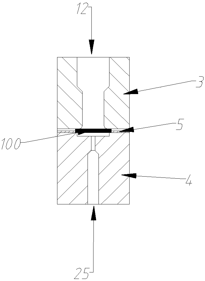
[0033] Such as figure 1 As shown, the new hydraulic inflation test fixture includes an upper fixture 1 , a lower fixture 2 , an upper sleeve 3 and a lower sleeve 4 .

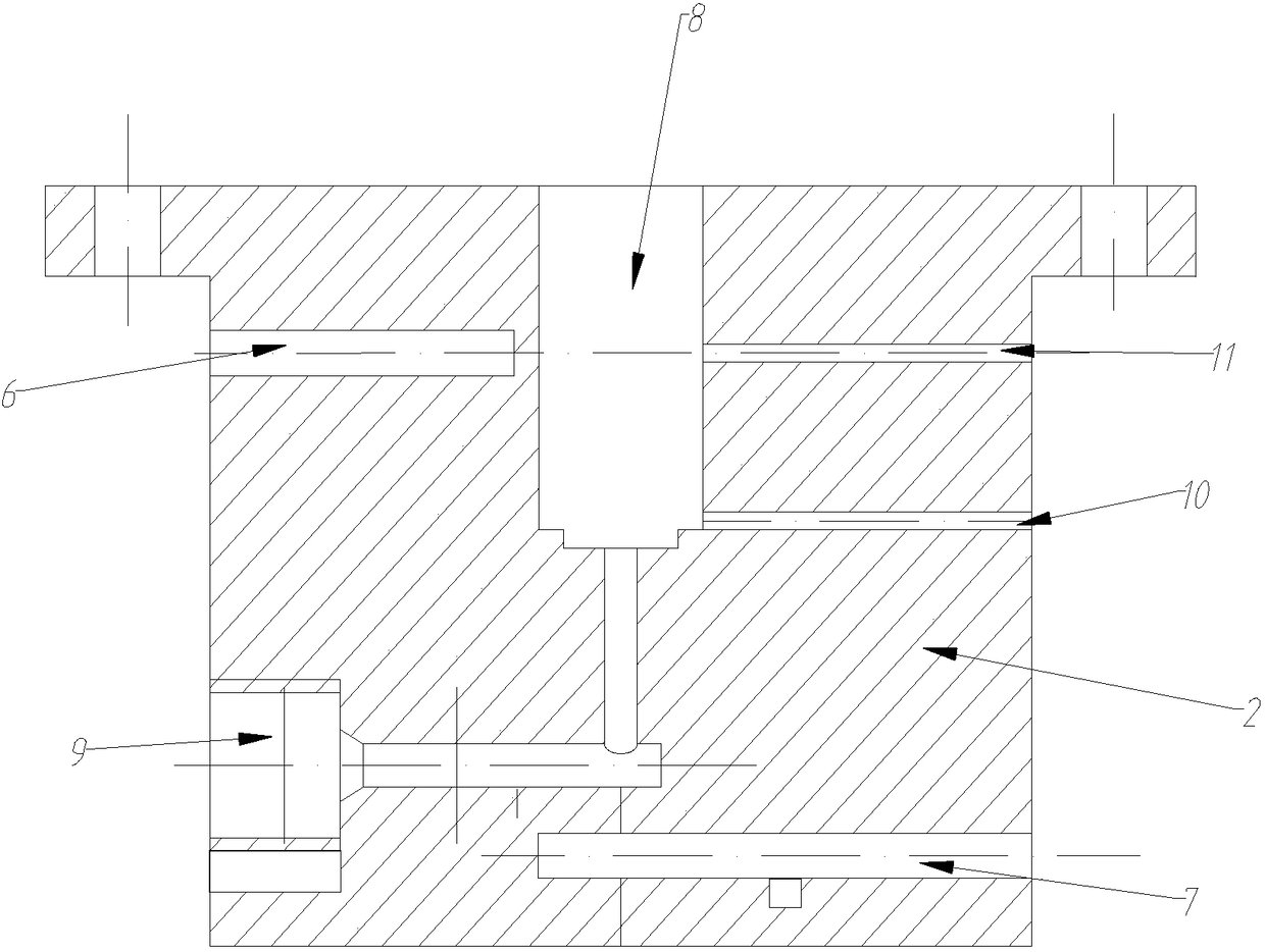
[0034] Such as figure 2 As shown, the lower fixture 2 is cylindrical, the upper edge of the lower fixture 2 is provided with a flange, and the flange and the lower fixture 2 body are integrally formed, and the center of the upper part of the lower fixture 2 is vertically provided with an inwardly extending installation cavity 8. The inner wall surface of the installation cavity 8 is smooth, and the installation cavity 8 is used to fix the upper sleeve 3 and the lower sleeve 4 . The installation cavity 8 is processed once, so as to ensure that the upper sleeve 3 and the lower sleeve 4 are coaxial. One side of the lower clamp 2 is respectively horizontally provided with a first oil drain passage 11 and a second oil drain passage 10 extending inward, and the first oil drain passage 11 and the second oil drain pa...

Embodiment 2

[0048] This embodiment is based on Embodiment 1, and the difference between this embodiment and Embodiment 1 is that a temperature-measuring blind hole 6 is horizontally arranged on the lower fixture 2 in this embodiment, and the diameter of the temperature-measuring blind hole 6 is 1 ~8mm, the hole depth of the temperature measuring blind hole 6 is 10-20mm smaller than the radius of the lower fixture 2, a temperature sensor can be installed in the temperature measuring blind hole 6 for measurement, and the temperature sensor is used to measure the temperature of the hydraulic oil in the test.

Embodiment 3

[0050] The structures of the lower clamp 2, the upper sleeve 3 and the lower sleeve 4 in this embodiment are the same as those in Embodiment 2. The difference between this embodiment and Embodiment 2 is that the upper clamp 1 in this embodiment only includes The upper fixture body 20, the upper fixture body 20 is a flange sealing plate, and the flange sealing plate is connected to the lower fixture 2 through a flange. The new hydraulic bulging test fixture in this embodiment is suitable for the situation where it is not necessary to measure the deformation of the sample 100 during the test. Compared with the new hydraulic bulging test fixture in Example 2, the new hydraulic bulging test fixture in this embodiment has a more structured structure. Simple and easy to install.


PUM

PropertyMeasurementUnit
thicknessaaaaaaaaaa

Abstract

The invention relates to a novel hydraulic bulging test clamp. The novel hydraulic bulging test clamp comprises an upper clamp, a lower clamp, an upper sleeve and a lower sleeve, the lower sleeve is provided with a first through hole, the upper sleeve is provided with a second through hole, and an inwardly-extending mounting chamber is arranged at the upper part of the lower clamp; an oil fillingchannel, a first oil leakage channel and a second oil leakage channel which extend inwardly and communicate with the mounting chamber are arranged in the side surface of the lower clamp; and the lowersleeve is mounted at the bottom of the mounting chamber, the upper sleeve is mounted at the upper part of the mounting chamber, the central axis of the second through hole and the central axes of thefirst through hole are on the same straight line, and the upper clamp is fixedly mounted above the lower clamp. The novel hydraulic bulging test clamp has the advantages of low loss of hydraulic oil,short clamp cleaning time, convenience in installation, high measurement precision and high safety.

Description

technical field [0001] The invention relates to the technical field of experimental equipment, in particular to a novel hydraulic bulging test fixture. Background technique [0002] Micro-specimen testing technology has developed rapidly in the past three decades, and the most remarkable thing in this field is the small punch test technology. Now this technology has begun to be used to measure various mechanical parameters such as elastoplastic properties, fracture toughness, and ductile-brittle transition temperature of materials, and it has also begun to play a role in the research of creep and damage. Moreover, the United States, the European Union, Japan Both China and China have formulated relevant technical standards. [0003] Hydraulic bulging test technology is a new type of micro-sample testing technology. The hydraulic bulging test mechanism is similar to the bursting disc test mechanism. It uses hydraulic oil to drive the deformation of small samples to obtain ma...

Claims


Application Information

Patent Timeline
Patent Type & Authority Applications(China)
IPC IPC(8): G01N3/04
CPCG01N3/04G01N2203/0411
Inventor 王汉奎徐彤张雪涛邹建胜
Owner CHINA SPECIAL EQUIP INSPECTION & RES INST
Why Eureka
Try Eureka