Neutron generator neutron yield control system and method

A technology of a neutron generator and a control method, which is applied in control/regulation systems, instruments, DC voltage accelerators, etc., can solve the problems of fluctuation of neutron yield, reduction of capacitance value of silicon stack capacitor, and reduction of neutron yield, etc. Achieve the effect of stable neutron yield output

Active Publication Date: 2020-09-29
BC P INC CHINA NAT PETROLEUM CORP +1
View PDF6 Cites 1 Cited by
  • Summary
  • Abstract
  • Description
  • Claims
  • Application Information

AI Technical Summary

Problems solved by technology

However, the output of D-T neutron generator fluctuates greatly due to the influence of neutron tube life and high temperature working environment, which has a certain impact on the accuracy of its measurement parameters. The main impact mechanism includes: increasing the neutron output with the cumulative working time The high-temperature ignition of neutron tubes leads to drastic fluctuations in neutron output. Under high-temperature environments, the capacitance of the silicon stack of the voltage-doubling pup joint decreases, and the insulation performance of insulating materials decreases, resulting in a decrease in neutron output. Therefore, D-T neutron The neutron yield of the generator is controlled

Method used


Image

  • Neutron generator neutron yield control system and method
  • Neutron generator neutron yield control system and method
  • Neutron generator neutron yield control system and method

Examples


Embodiment Construction

[0026] The present invention is described in further detail below in conjunction with accompanying drawing:

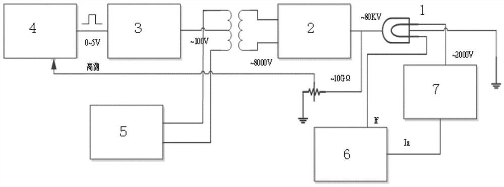
[0027] Such as figure 1 As shown, the neutron yield control system of the neutron generator according to the present invention includes a neutron tube 1, a voltage doubling nipple 2, a linear power supply module 3, a generator high voltage control circuit 4, a generator high voltage drive circuit 5, Ion source circuit 6, anode high voltage module 7 and step-up transformer.

[0028] A voltage-resistant high-resistance resistor of about 10GΩ is installed in the voltage doubler joint 2. The output terminal of the generator control circuit 4DA is connected to the control input terminal of the linear power supply module 3, and the output terminal of the linear power supply module 3 is connected to the center tap input of the step-up transformer. The output terminals of the high-voltage drive circuit 5PWM wave are respectively connected to the input terminals of the step-up...


PUM


Abstract

The invention discloses a neutron generator neutron yield control system and method. A resistor is arranged in a voltage-multiplying pup joint, the output end of the voltage-multiplying pup joint is grounded and connected with a neutron tube target pressure end, and the voltage-multiplying pup joint target voltage output end is connected with the input end of a generator high-voltage control circuit; the high-voltage output end of an anode high-voltage module is connected with the anode end of the neutron tube; the negative electrode end of the anode high-voltage module is connected to the anode current Ia acquisition end of an ion source circuit; a filament circuit of the ion source circuit is connected with a neutron tube filament end; a control chip is arranged in the generator high-voltage control circuit, the DA output end of the generator high-voltage control circuit is connected with the control input end of the linear power module, the output end of the linear power module is connected with the center tap input end of a boosting transformer, and the PWM wave output end of the high-voltage drive circuit is connected with the input end of the boosting transformer. The outputend of the boosting transformer is connected with the input end of the voltage-multiplying circuit. The neutron generator can be controlled to maintain high-stability neutron yield output.

Description

technical field [0001] The invention belongs to the field of oil and gas drilling, and relates to a neutron yield control system and method for a neutron generator. Background technique [0002] The radioactive logging technology at home and abroad is developing towards the trend of passive green logging; the 14MeV fast neutrons generated by the D-T neutron generator can replace the Cs-137 and Am-Be chemical sources, and the thermal neutron lifetime can be realized , porosity, density, and radioactive global logging of formation elements. However, the output of D-T neutron generator fluctuates greatly due to the influence of neutron tube life and high temperature working environment, which has a certain impact on the accuracy of its measurement parameters. The main impact mechanism includes: increasing the neutron output with the cumulative working time The high-temperature ignition of neutron tubes leads to drastic fluctuations in neutron output. Under high-temperature env...

Claims


Application Information

Patent Timeline
Patent Type & Authority Applications(China)
IPC IPC(8): G05F1/56H05H3/06
CPCG05F1/561H05H3/06
Inventor 安旅行陈辉朱军骆庆锋陈绪涛王珺郭广鎏宋森范宇翔袁晓波
Owner BC P INC CHINA NAT PETROLEUM CORP
Why Eureka
Try Eureka