Supercharge Your Innovation With Domain-Expert AI Agents!

led display module

一种LED显示器、显示模块的技术,应用在静态指示器、辨认装置、仪器等方向,能够解决形成通孔、机械强度低、没有提出LED显示结构等问题

Active Publication Date: 2022-04-12
TETOS VACUUM EQUIP (JIANGSU) CO LTD
View PDF23 Cites 0 Cited by
  • Summary
  • Abstract
  • Description
  • Claims
  • Application Information

AI Technical Summary

Problems solved by technology

[0008] figure 1 The LED display shown in (b) in has the following disadvantages: the mechanical strength is so low that the substrate may crack when the substrate is made of glass, and through-holes need to be formed, thus requiring considerable time, effort, and cost in manufacturing
However, an LED display structure in which a screen is configured without a bezel and wiring for supplying power and / or signals is formed on a side portion of a substrate has not been proposed so far.

Method used


Image

  • led display module
  • led display module
  • led display module

Examples


Embodiment Construction

[0023] Hereinafter, embodiments of the apparatus for helping toilet users to stand according to the present disclosure will be described in detail with reference to the accompanying drawings, which have the aforementioned objectives, solutions and effects.

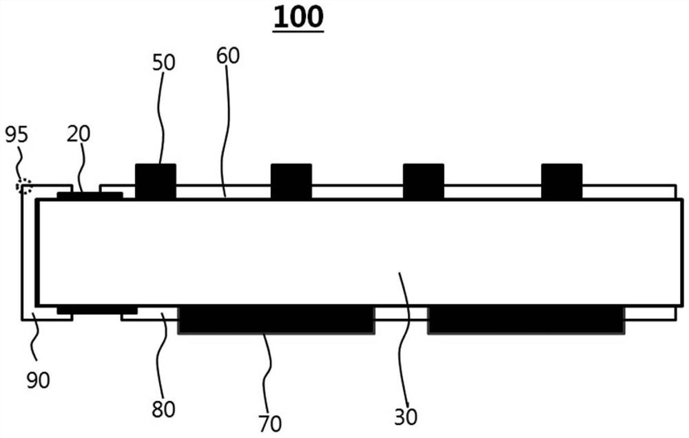
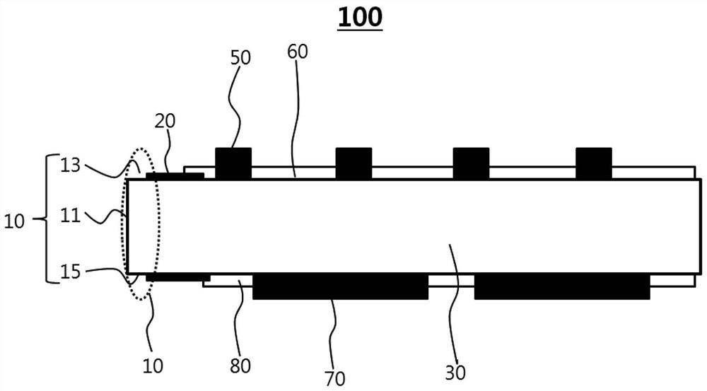
[0024] figure 2 is a schematic cross-sectional view of a light emitting diode (LED) display module according to an embodiment of the present disclosure.

[0025] Such as figure 2 As shown, the LED display module 100 according to the embodiment of the present disclosure includes: a substrate 30, a plurality of display devices 50 mounted on the top side of the substrate 30, an upper circuit pattern 60 formed on the top side of the substrate 30, mounted on the substrate The controller device 70 on the top or bottom side of the substrate 30 , the lower circuit pattern 80 formed on the bottom side of the substrate 30 , and the side wiring 90 electrically connecting the upper circuit pattern 60 and the lower circuit pattern 8...


PUM


Abstract

The present disclosure relates to an LED display module, and more specifically, to an LED display module in which a conductive metal film layer formed by deposition is used to configure side wiring to connect an upper circuit pattern and a lower circuit pattern of a substrate, thereby removing the frame , and because even when multiple modules are spliced ​​to obtain the required display size, no dividing lines or border lines are visible, thus ensuring display quality.

Description

technical field [0001] The present disclosure relates to a light emitting diode (LED) display module, and more particularly, to an LED display module in which a conductive metal thin film layer formed by deposition is used to configure side wiring to connect an upper circuit pattern and a lower circuit of a substrate pattern, thereby eliminating borders and maintaining display quality, as no dividing lines or border lines are visible even when multiple modules are spliced ​​to obtain the desired display size. Background technique [0002] Micro light-emitting diodes (LEDs) refer to ultra-small LEDs, whose structure is similar to that of traditional LEDs, but the microscopic size of the chip is 10-100 μm, and it can be used to display pixels of products. Compared with traditional LEDs, micro LEDs have high contrast, have advantages in response speed and viewing angle, and have excellent brightness and extreme resolution. In addition, micro LEDs are superior in chemical and m...

Claims


Application Information

Patent Timeline
Patent Type & Authority Patents(China)
IPC IPC(8): G09F9/33H01L25/16
CPCG09F9/33H01L25/167H01L25/0753H01L33/62H05K3/403G09G3/32H05K2201/10106H05K1/181H05K2201/09409H01L33/48H01L21/768H01L33/20H01L33/38
Inventor 宋根浩
Owner TETOS VACUUM EQUIP (JIANGSU) CO LTD
Features
  • R&D
  • Intellectual Property
  • Life Sciences
  • Materials
  • Tech Scout
  • Unparalleled Data Quality
  • Higher Quality Content
  • 60% Fewer Hallucinations
Learn More