Template positioning device for circuit board production

A positioning device and circuit board technology, which is applied to printed circuits, printed circuit manufacturing, printed circuit assembly of electrical components, etc., can solve the problems of lower printing quality, less tin on circuit boards, time-consuming and labor-intensive problems, and achieve uniform force and ensure The effect of stability

Active Publication Date: 2020-09-29
DEZHOU UNIV
View PDF2 Cites 2 Cited by
  • Summary
  • Abstract
  • Description
  • Claims
  • Application Information

AI Technical Summary

Problems solved by technology

When actually brushing the stencil by hand, the position between the stencil and the empty circuit board is very important. If there is a gap between them, the printed circuit board will have less tin, even tin, and uneven thickness of the solder paste. A series of defects occur, which greatly reduces the printing quality. Therefore, when brushing solder paste manually, the operator generally needs to apply a certain amount of force to ensure the adhesion between the steel mesh and the circuit board, which is time-consuming and laborious.

Method used


Image

  • Template positioning device for circuit board production
  • Template positioning device for circuit board production
  • Template positioning device for circuit board production

Examples


Embodiment 1

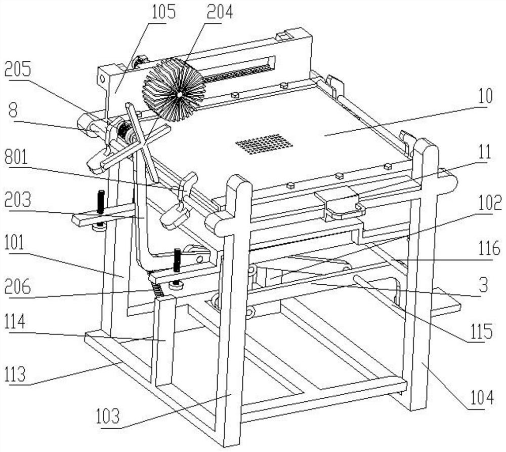
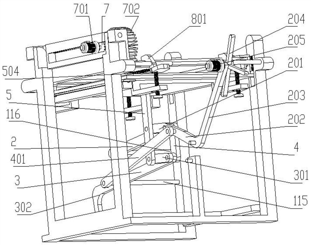
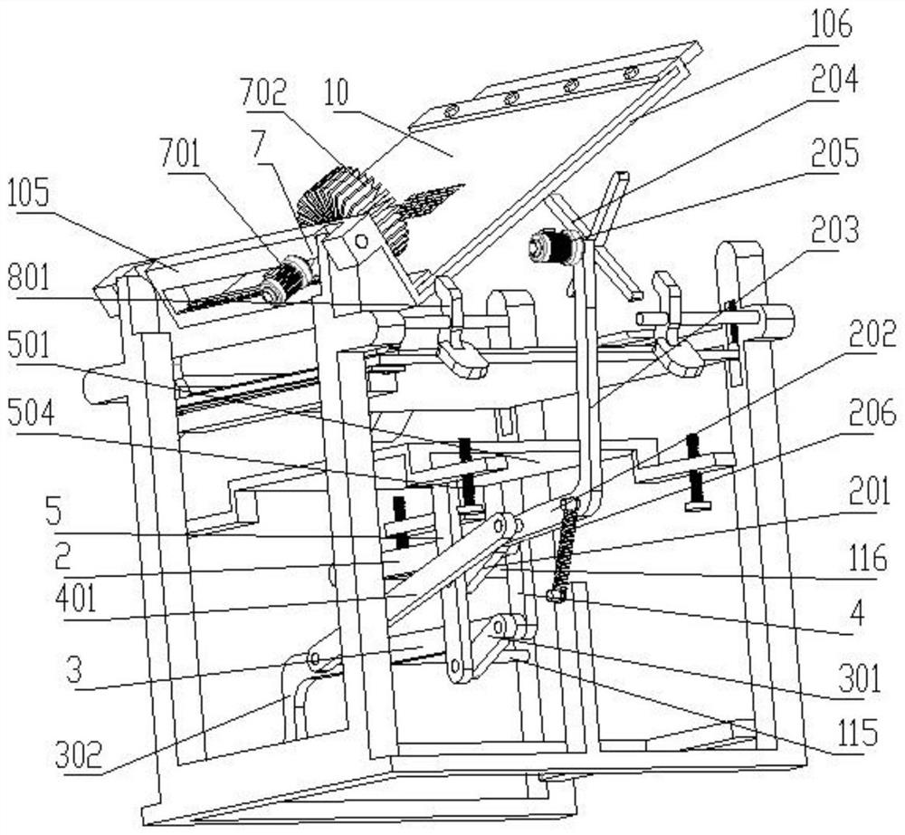
[0034] see Figure 1-Figure 8 , a template positioning device for circuit board production, including a printing pad, the printing pad includes symmetrically arranged column one 101 and column two 102, column three 103 and column four 104, and the outer sides of the column one 101 and column two 102 are hingedly provided with a vertical plate 105 , the inner side of the lower end of the vertical plate 105 is fixedly provided with a rectangular frame 106, the outer side of the other end of the rectangular frame 106 is fixedly provided with an external connection plate 112, a fixed plate is arranged between the top of the column three 103 and the column four 104, and the external connection plate 112 is lapped on On the fixed plate 119 and the rectangular frame 106 is horizontal;

[0035] On the printing pad and directly below the rectangular frame 106, a placement plate 6 is arranged, and sliding columns 602 are arranged symmetrically at both ends of the opposite sides of the p...

Embodiment 2

[0047] see Figure 1-Figure 8 , a template positioning device for circuit board production, including a printing pad, the printing pad includes symmetrically arranged column one 101 and column two 102, column three 103 and column four 104, and the outer sides of the column one 101 and column two 102 are hingedly provided with a vertical plate 105 , the inner side of the lower end of the vertical plate 105 is fixedly provided with a rectangular frame 106, the outer side of the other end of the rectangular frame 106 is fixedly provided with an external connection plate 112, a fixed plate is arranged between the top of the column three 103 and the column four 104, and the external connection plate 112 is lapped on On the fixed plate 119 and the rectangular frame 106 is horizontal;

[0048] On the printing pad and directly below the rectangular frame 106, a placement plate 6 is arranged, and sliding columns 602 are arranged symmetrically at both ends of the opposite sides of the p...


PUM


Abstract

The invention provides a template positioning device for circuit board production and belongs to the technical field of circuit board manufacturing. An ink pad comprises a first stand column, a secondstand column, a third stand column and a fourth stand column which are symmetrically arranged, wherein vertical plates are hinged to outer sides of the first stand column and the second stand column,rectangular frames are fixedly arranged on inner sides of lower ends of the vertical plates, external connection plates are fixedly arranged on outer sides of the other ends of the rectangular frames, fixing plates are arranged between upper portions of the third stand column and the fourth stand column, a placement plate is arranged on the ink pad and located under the rectangular frames, an upper swing rod is rotationally arranged on a first polished shaft, a lower swing rod is rotationally arranged on a second polished shaft, the other end of the upper swing rod is connected with the otherend of the lower swing rod through a first connecting rod, an upper rocker is hinged to the other side, opposite to the first connecting rod, of the upper swing rod, a lower rocker is hinged to the other side, opposite to the first connecting rod, of the lower swing rod, and a limiting plate is arranged below a placing plate. The device is advantaged in that the device assists workers in positioning and fixing the position of a circuit board.

Description

technical field [0001] The invention relates to the technical field of circuit board manufacturing, in particular to a template positioning device for circuit board production. Background technique [0002] PCB (Printed Circuit Board, printed circuit board), also known as printed circuit board, is an important electronic component. As the support of electronic components, the printed circuit board is the carrier of the electrical connection of electronic components. Because the circuit boards are made using electronic printing, they are called "printed" circuit boards. At present, large-scale circuit board manufacturing enterprises all use automated machinery for production, but some individuals or small enterprises still use manual manufacturing for production. In the manual production process, the most important task is to manually brush the stencil ( That is, brushing solder paste). The stencil, also known as the SMT template, is a special mold for SMT. Its main functi...

Claims


Application Information

Patent Timeline
Patent Type & Authority Applications(China)
IPC IPC(8): H05K3/30H05K3/34
CPCH05K3/303H05K3/341
Inventor 王振岭王伟张俊亮
Owner DEZHOU UNIV
Why Eureka
Try Eureka