Raw material mixing device for health-care product production

A technology for mixing devices and health products, which is applied in the field of raw material mixing devices for health products production, and can solve problems such as poor mixing effect, small operating range of the stirring rod, and limited blanking speed, etc.

Inactive Publication Date: 2020-10-02
杨丽娟
View PDF1 Cites 2 Cited by
  • Summary
  • Abstract
  • Description
  • Claims
  • Application Information

AI Technical Summary

Problems solved by technology

However, the position of the stirring rod set by the raw material mixing device for the production of health care products is fixed, so the raw materials at the fixed position inside the first housing can only be stirred and mixed, and the operating range of the stirring rod is too small to cause a poor stirring effect; In addition, it only feeds through the through pipe, and the feeding speed is limited. When the raw material passes through the mesh of the third shell, it is easy to block the mesh

Method used


Image

  • Raw material mixing device for health-care product production
  • Raw material mixing device for health-care product production
  • Raw material mixing device for health-care product production

Examples


Embodiment 1

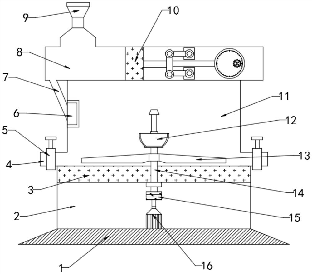
[0025] see figure 1 , in Embodiment 1 of the present invention, a raw material mixing device for production of health care products, which includes: a device body, which is divided into a temporary storage box 8, a mixing chamber 11, and a load-bearing box 2 from top to bottom. The upper end of the temporary storage box 8 is connected to the feed hopper 9, and a feeding assembly 10 is fixed inside the temporary storage box 8. The lower end of the temporary storage box 8 is connected to the mixing chamber 11 through the feeding pipe 7, and the mixing chamber 11 is left The filter frame 6 is installed and fixed on the side inner wall, and the lower end of the feed pipe 7 extends to the filter frame 6; the inside of the mixing chamber 11 is provided with a stirring assembly 12, and the stirring assembly 12 is driven by a driving assembly, and the left and right sides of the lower end of the mixing chamber 11 Connect the discharge pipe 4, the discharge pipe 4 is fixed with a disch...

Embodiment 2

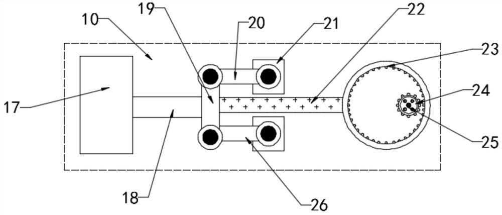
[0029] see figure 2 Further, the feed assembly 10 includes a piston 17, a crank 19, a movable rod 22, a large toothed plate 23 and a driving toothed plate 24, the piston 17 is movably installed inside the temporary storage box 8, and one end of the piston 17 is connected with the push rod 18 The crank 19 is connected, and the upper and lower ends of the crank 19 are hinged and movable respectively with one end of the first rotating handle 20 and one end of the second rotating handle 26 through pin shafts, and the other end of the first rotating handle 20 and the other end of the second rotating handle 26 are all movable installed on the On the fixed block 21; the middle of the crank 19 is connected with the large toothed plate 23 through the movable rod 22, the inner wall of the large toothed plate 23 is engaged with the driving toothed plate 24, and the driving shaft 25 is installed in the middle of the driving toothed plate 24;

[0030] Start the drive shaft 25, the drive s...

Embodiment 3

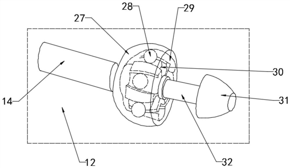
[0035] see image 3 with Figure 4 , the stirring assembly 12 includes a connection end 27, a movable end, a stirring rod 32 and a stirring end 31, one end of the connection end 27 is connected and fixed to the rotating shaft 14, and the movable end is movably installed inside the connection end 27, and the movable end The other end of the head is provided with a stirring rod 32, and one end of the stirring rod 32 is fixed with a stirring end 31;

[0036] Specifically, a movable groove 29 is provided inside the connecting terminal 27, and the movable terminal is movably installed in the movable groove 29 provided inside the connecting terminal 27;

[0037] Furthermore, a rolling rail 30 is provided on the edge of the movable end, and a ball 28 is rollingly installed inside the rolling rail 30, and the rolling ball 28 installed inside the rolling rail 30 is in surface contact with the movable groove 29 provided inside the connecting end 27;

[0038] When the rotating shaft 14 d...


PUM


Abstract

The invention relates to the field of health-care product production equipment, in particular to a raw material mixing device for health-care product production. The device comprises a device body, wherein the device body is sequentially divided into a temporary storage box, a mixing cavity and a bearing box from top to bottom, the upper end of the temporary storage box communicates with a feedinghopper, a feeding assembly is fixedly installed in the temporary storage box, the lower end of the temporary storage box communicates with the mixing cavity through a feeding pipe, a filtering frameis fixedly installed on the inner wall of the left side of the mixing cavity, and the lower end of the feeding pipe extends to the filtering frame. A stirring assembly is arranged in the mixing cavityand is driven by a driving assembly to operate. When the connecting end of the stirring assembly rotates at a high speed, centrifugal force can be generated, a movable end installed in the connectingend deflects through a movable groove formed in the connecting end, then the inclination degree of a stirring rod is changed, and the whole stirring assembly can fully stir and mix raw materials at different positions of the bottom end of the device body.

Description

technical field [0001] The invention relates to the field of health product production equipment, in particular to a raw material mixing device for health product production. Background technique [0002] Health food is a popular term for health food. Article 3.1 of GB16740-97 "General Standards for Health (Functional) Foods" defines health food as: health (functional) food is a type of food, which has the commonality of general food and can regulate the human body. It is suitable for consumption by specific groups of people, but not for the purpose of treating diseases. In the existing production process of health care products, the raw materials need to be mixed, and then the production of health care products is carried out; on the one hand, the existing raw material mixing device does not have certain filtering equipment, which cannot maintain the purity of the raw materials; on the other hand, the current mixing device is only a single Direction rotation cannot make th...

Claims


Application Information

Patent Timeline
Patent Type & Authority Applications(China)
IPC IPC(8): B01F7/16B01F7/18B01F15/00B01F15/02B01F3/20B01F23/70
CPCB01F23/708B01F27/11B01F27/80B01F27/90B01F35/187B01F35/71B01F2101/23
Inventor 杨丽娟
Owner 杨丽娟
Why Eureka
Try Eureka