Copper bar production and manufacturing stretching equipment and copper bar production and manufacturing stretching process

A technology of drawing equipment and copper rods, applied in the field of copper rod manufacturing drawing equipment and copper rod manufacturing drawing process, can solve the problems of increased workload, increased damage to molds, and collision of blanks by molds, etc. Achieve the effect of improving work efficiency, reducing collision and reducing friction

Inactive Publication Date: 2020-10-02
台州蓝锐机电科技有限公司
View PDF0 Cites 4 Cited by
  • Summary
  • Abstract
  • Description
  • Claims
  • Application Information

AI Technical Summary

Problems solved by technology

[0003] However, the copper rods have the following problems in the process of extrusion molding at present: one, the traditional extrusion dies will have blanks that are subjected to the collision of the mold during processing, which cannot ensure that the copper rods after molding meet the requirements for use, so copper rods need to be processed Secondary processing, increasing unnecessary workload
[0004] 2. The usual extrusion dies use a sliding fit to process the billet, which will increase the damage to the die, and cause defects on the surface of the workpiece during processing, which will affect the use

Method used


Image

  • Copper bar production and manufacturing stretching equipment and copper bar production and manufacturing stretching process
  • Copper bar production and manufacturing stretching equipment and copper bar production and manufacturing stretching process
  • Copper bar production and manufacturing stretching equipment and copper bar production and manufacturing stretching process

Examples


Embodiment Construction

[0031] The embodiments of the present invention will be described in detail below with reference to the accompanying drawings, but the present invention can be implemented in many different ways defined and covered by the claims.

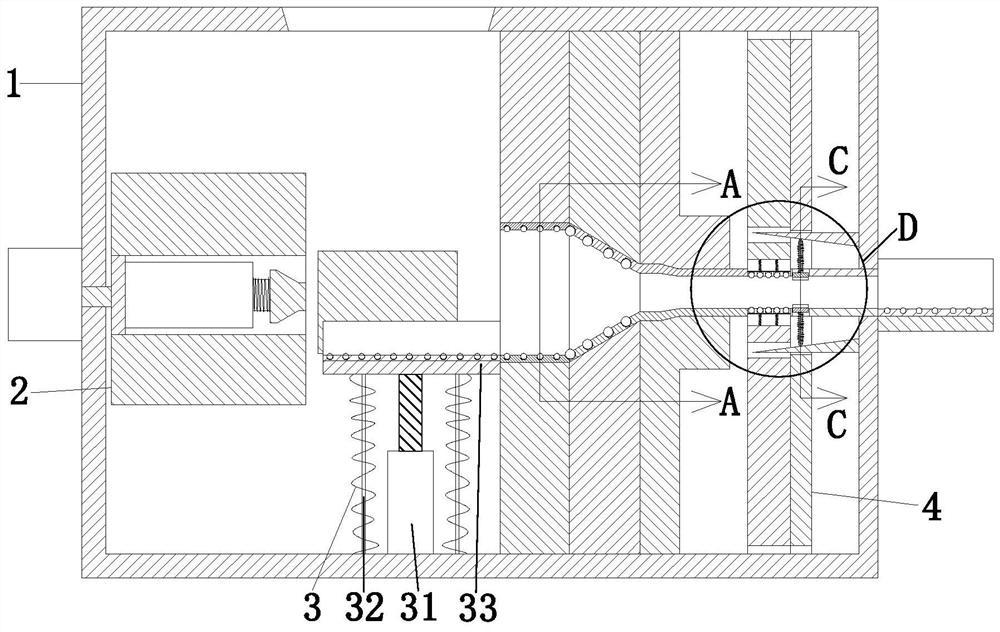
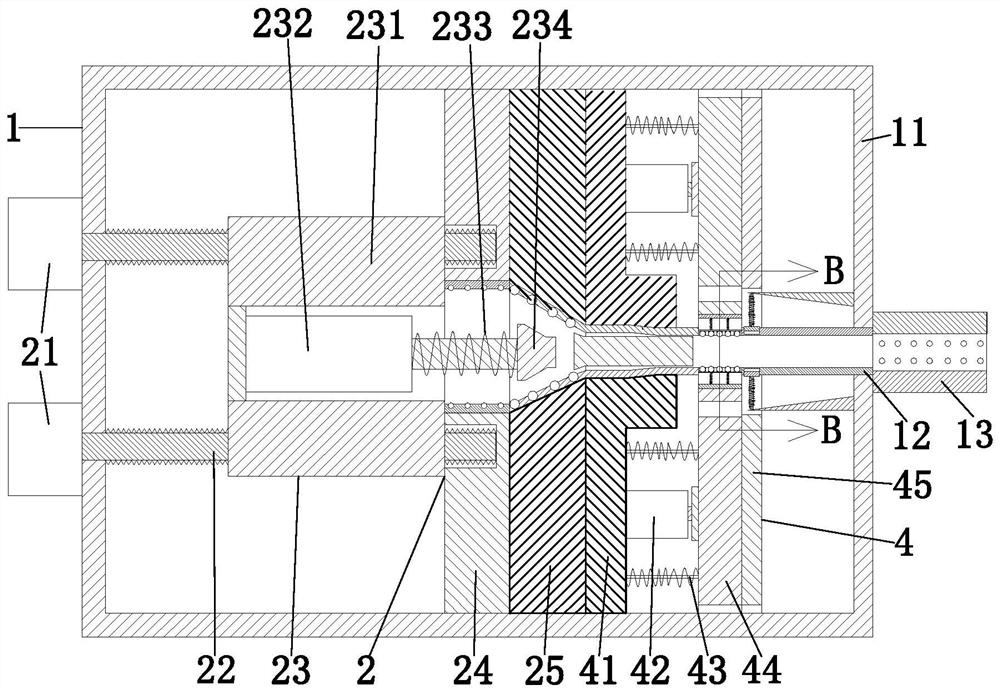
[0032] Such as Figure 1 to Figure 6 A kind of drawing equipment for manufacturing copper rods shown includes a processing shell 1, an extruding unit 2, a feeding unit 3, and a shaping unit 4. The upper side of the processing shell 1 is provided with a feed port, and the processing shell 1 An extrusion unit 2 is arranged on the inner wall of the body 1, a feeding unit 3 is arranged in the middle of the extrusion unit 2, and a shaping unit 4 is arranged on the right side of the extrusion unit 2, wherein:

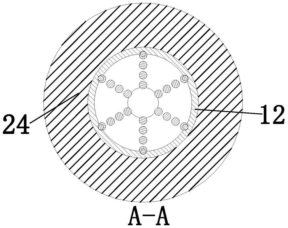
[0033] The processing shell 1 includes a processing shell 11, a hollow processing tube 12, and a hopper 13, wherein the hollow processing tube 12 is arranged on the inner wall of the right middle part of the processing shell 11, and the hopper 13 i...


PUM


Abstract

The invention provides copper bar production and manufacturing stretching equipment and a copper bar production and manufacturing stretching process. The copper bar production and manufacturing stretching equipment comprises a machining shell, an extrusion unit, a feeding unit and a shaping unit, wherein a feeding port is formed in the upper side of the machining shell, the extrusion unit is arranged on the inner wall of the machining shell, the feeding unit is arranged in the middle of the extrusion unit, and the shaping unit is arranged on the right side of the extrusion unit. According to the copper bar production and manufacturing stretching equipment, the feeding unit is additionally arranged, a heated blank can be lifted to the same height as an extrusion die, and then extrusion machining is conducted on the blank, so that collision is reduced, and the working efficiency is improved; and balls are arranged on the machining shell, the extrusion unit, the feeding unit and the shaping unit correspondingly, so that friction between a blank and the die during machining is effectively reduced, machining is more convenient and faster, and a certain protection effect is achieved on the extrusion die.

Description

technical field [0001] The invention relates to the technical field of copper rod production, in particular to a copper rod manufacturing stretching equipment and a copper rod manufacturing stretching process. Background technique [0002] In the processing and molding of copper rods, extrusion molding is more common. Extrusion molding generally refers to heating the billet to a certain temperature, putting it into an extrusion mold, and extruding the raw material with a piston or screw by applying pressure. , in order to realize the processing method of extrusion molding. [0003] However, the copper rods have the following problems in the process of extrusion molding at present: one, the traditional extrusion dies will have blanks that are subjected to the collision of the mold during processing, which cannot ensure that the copper rods after molding meet the requirements for use, so copper rods need to be processed Secondary processing increases unnecessary workload. ...

Claims


Application Information

Patent Timeline
Patent Type & Authority Applications(China)
IPC IPC(8): B21C23/08B21C23/21B21C25/02B21C33/00
CPCB21C23/08B21C23/21B21C23/211B21C23/212B21C25/02B21C33/00
Inventor 苏刚付子豪
Owner 台州蓝锐机电科技有限公司
Why Eureka
Try Eureka