Welding equipment for precision instrument machining
A technology for welding equipment and precision instruments, applied in the field of precision instrument processing and welding equipment, can solve the problems of inability to weld the body and the joints, affecting normal work, easy to loosen, etc., so as to save manual fixation, improve practicability, and avoid falling off Effect
- Summary
- Abstract
- Description
- Claims
- Application Information
AI Technical Summary
Problems solved by technology
Method used
Image

Examples
Embodiment 1
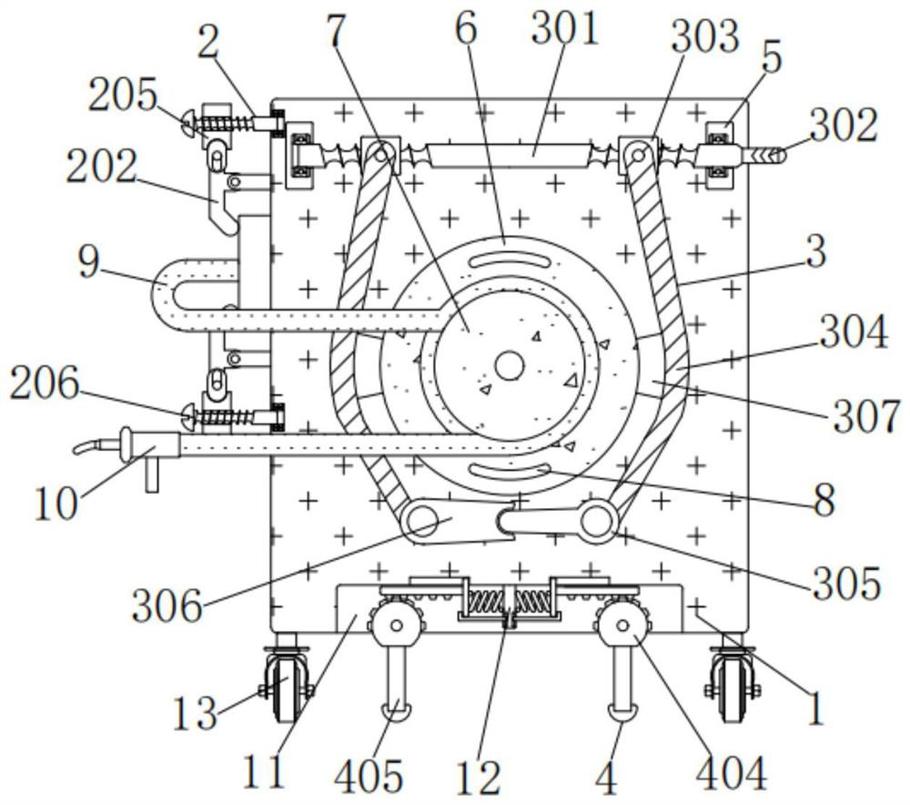
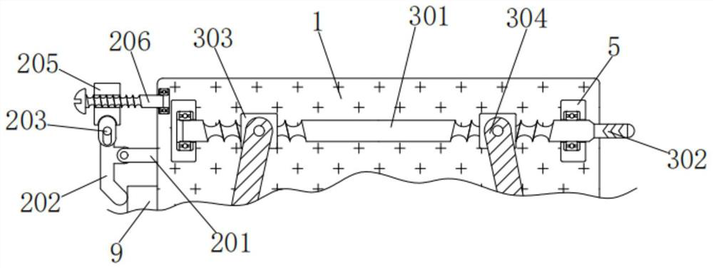
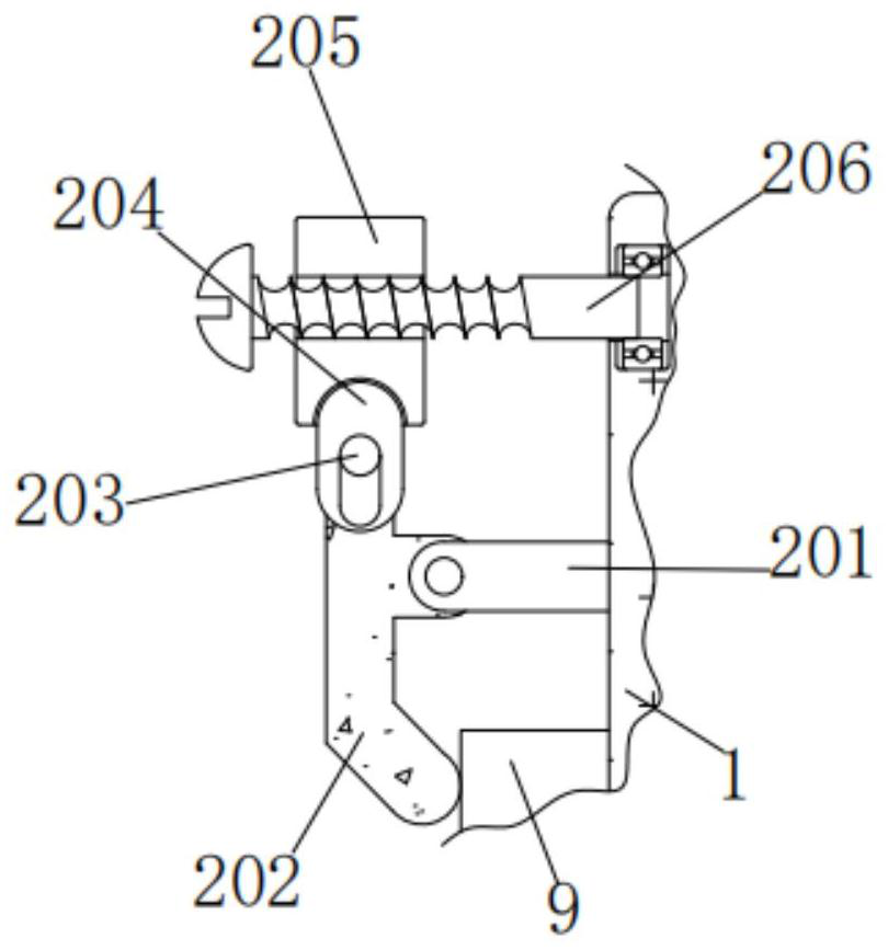
[0033] A welding equipment for precision instrument processing, including a welding body 1, the left side of the welding body 1 is electrically connected above the outer wall of the connecting line 9, the model of the welding body 1 is ZX7-400, the left side of the welding mechanism 1 is up and down Fixing mechanism 2 is installed, and fixing mechanism 2 comprises straight plate 201, curved plate 202, round rod 203, short plate 204, square 205 and bolt 206, and the right side of straight plate 201 is fixedly connected with the upper left side of welding body 1, and straight plate 201 The left side of the curved plate 202 is connected to the front rotation of the curved plate 202, and the curved plate 202 is rotated through the pin shaft on the left side of the straight plate 201. Sliding and clamping with the inner wall of the short board 204, the round rod 203 is forced to slide up and down through the inner wall of the short board 204, the top of the short board 204 is movabl...
Embodiment 2
[0035] As an option, see figure 1 , 2 And 4, used for precision instrument processing welding equipment, the front of the welding body 1 is rotatably connected with a disc 6, and the disc 6 is rotated through the front pin shaft of the welding body 1 under force, and the front of the disc 6 is fixedly connected with a sheave 7 , the outer wall of the connection line 9 is wound and connected with the outer wall of the sheave 7, and when the disc 6 rotates to drive the sheave 7, the connection line is wound or scattered to both sides at the same time, and the left side of the outer wall of the connection line 9 is connected with a welding torch 10, and the welding torch 10 The material is 18AK, and handles 8 are fixedly connected to the upper and lower sides of the front of the disc 6. The handle 8 is convenient for rotating the disc 6. The upper, left and right sides of the front of the welding body 1 are fixed with vertical plates 5, and the two vertical plates 5 Inner wall i...
Embodiment 3
[0038] As an option, see figure 1 , 5 And 6, used for precision instrument processing and welding equipment, the left and right sides of the vertical plate 12 are all equipped with a limit mechanism 4, the limit mechanism 4 includes a spring 401, a thin plate 402, a rack 403, a gear 404, a thick rod 405, and a rubber sleeve 406 and the curved plate 407, the inner sides of the two springs 401 are fixedly connected to the left and right sides of the vertical plate 12 respectively, and the outer sides of the two springs 401 are fixedly connected to the inner sides of the thin plate 402 respectively, and the thin plate 402 moves under force through the spring 401. Rebound, the tops of the two thin plates 402 are slidingly engaged with the left and right sides of the inner wall top of the groove 11 respectively, the thin plates 402 slide left and right through the inner wall top of the groove 11 under force, and the outer sides of the two thin plates 402 are respectively connected ...
PUM
 Abstract
Description
Claims
Application Information
 - R&D
- Intellectual Property
- Life Sciences
- Materials
- Tech Scout
- Unparalleled Data Quality
- Higher Quality Content
- 60% Fewer Hallucinations
Browse by: Latest US Patents, China's latest patents, Technical Efficacy Thesaurus, Application Domain, Technology Topic, Popular Technical Reports.
© 2025 PatSnap. All rights reserved.Legal|Privacy policy|Modern Slavery Act Transparency Statement|Sitemap|About US| Contact US: help@patsnap.com