Wall grooving cutting device for architectural engineering construction

Inactive Publication Date: 2020-10-02
江苏宏尧建设有限公司
View PDF8 Cites 2 Cited by
  • Summary
  • Abstract
  • Description
  • Claims
  • Application Information

AI Technical Summary

Problems solved by technology

[0004] However, in actual use, the above-mentioned device generates a lot of dust and cannot simply switch the slot width. At the same time, they all use the same cutter to cut in parallel, so the slots cut out by them are also smooth enough, and there are no gaps in the cutting process. Debris and the like also have certain dangers to construction workers, which makes construction workers not only affect work efficiency but also cause greater damage to the human body during actual construction. Therefore, a new type of wall ditching device for construction engineering construction is now needed to optimize these issues

Method used


Image

  • Wall grooving cutting device for architectural engineering construction
  • Wall grooving cutting device for architectural engineering construction
  • Wall grooving cutting device for architectural engineering construction

Examples


Embodiment Construction

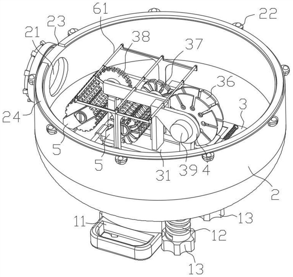
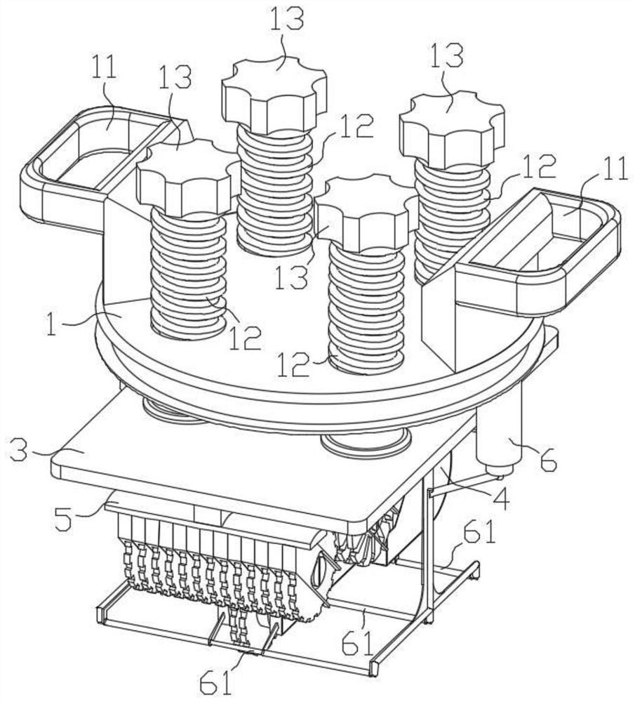
[0041] like figure 1 , 2 . As shown in 3, a wall ditching and cutting device for building engineering construction includes: a device main body, which includes a central carrier 1 and an annular casing 2, the annular casing 2 is rotationally connected with the central carrier 1, and the annular casing 2. The bottom surface is provided with an outlet 21 for slag discharge of the external charging bag. The four corners of the inner side of the cutting tool holder 3 are respectively provided with an adjusting screw 12 for limiting the height. The adjusting screw 12 is threadedly connected with the central carrier plate 1 and passed The adjustment knob 13 on the outer surface of the center carrier 1 is controlled. By setting the adjusting nut 12, the cutting depth of the cutter holder 3 can be effectively and quickly adjusted, and the control is simple and effective. There are two groups of handles 11 arranged symmetrically and parallelly on the outer surface of the central carr...


PUM


Abstract

The invention discloses a wall grooving cutting device for architectural engineering construction. A device body comprises a central carrier plate and an annular housing which is rotationally connected with the central carrier plate; a cutter rest is connected with the inner side surface of the central carrier plate in threaded and ascending-descending modes; sliding pieces which are used for adjusting the interval are disposed on the two sides of the cutter rest symmetrically; a wire groove rod, a crushing rod and a grinding rod are sequentially disposed in the front, the middle and the backof each sliding piece; the two wire groove rods are connected with wire groove saw blades correspondingly through transmission shafts, the two crushing rods are connected with crushing saw blades correspondingly through transmission shafts, and the two grinding rods are connected with grinding wheel pieces correspondingly through transmission shafts; transmission rods are in transmission connection through transmission assemblies; and an extensible cutter rest which is used for increasing the width of a crushing area is disposed in the position, located in rear of the crushing saw blades, of the lower bottom surface of the cutter rest, and an extensible cutter rest which is used for increasing the width of a grinding area is disposed in the position, located in rear of the grinding wheel pieces, of the lower bottom surface of the cutter rest. By means of the wall grooving cutting device for architectural engineering construction, the construction safety of workers can be improved, meanwhile the requirement of multi-width wall grooving construction can be met, and wall grooving is safe and efficient.

Description

technical field [0001] The invention relates to the technical field of mechanical grooving equipment, in particular to a wall ditching and cutting device for building engineering construction. Background technique [0002] Wall trenching and cutting is a construction method for slotting, wiring and piping on the wall during the construction process. Traditional wall cutting requires first cutting out the line seams and then chiseling out the line slots with an electric hammer. This method is complicated to operate. , Low efficiency, greater damage to the wall. [0003] With the continuous development, there are many types of wall slotting machines, and most of the wall slotting methods are combined with multiple saw blades, which greatly optimizes the traditional Wall slotting method. [0004] However, in actual use, the above-mentioned device generates a lot of dust and cannot simply switch the slot width. At the same time, they all use the same cutter to cut in parallel,...

Claims


Application Information

Patent Timeline
Patent Type & Authority Applications(China)
IPC IPC(8): B28D1/04B28D7/00B28D7/02B02C21/00
CPCB02C21/00B02C2201/06B28D1/045B28D1/048B28D7/00B28D7/005B28D7/02
Inventor 曹胜峰张中明刁茂祥刘兵刘宁杨凯
Owner 江苏宏尧建设有限公司
Why Eureka
Try Eureka