
Dynamic wireless charging method and device for electric vehicle on photovoltaic road

An electric vehicle and wireless charging technology, applied in electric vehicle charging technology, electric vehicles, circuit devices, etc., can solve the problems of unsatisfactory driving range, electric vehicle charging, and limitation of electric vehicle charging convenience, etc. The effect of driving mileage, saving transportation costs, and saving charging time

Inactive Publication Date: 2020-10-02
JIANGSU UNIV
View PDF5 Cites 2 Cited by
  • Summary
  • Abstract
  • Description
  • Claims
  • Application Information

AI Technical Summary

Problems solved by technology

But the problem also comes with it, that is, the problem of charging electric vehicles
The current driving range of electric vehicles is mostly unsatisfactory, and the distribution and quantity of charging piles in cities and the convenience of use also greatly limit the convenience of electric vehicle charging, and at the same time, the long charging time cannot make electric vehicles as traditional. The mileage of fuel vehicles is updated so quickly, and the incident of spontaneous combustion of some electric vehicles while charging is also shocking.

Method used


Image

  • Dynamic wireless charging method and device for electric vehicle on photovoltaic road
  • Dynamic wireless charging method and device for electric vehicle on photovoltaic road
  • Dynamic wireless charging method and device for electric vehicle on photovoltaic road

Examples


Embodiment Construction

[0031] In order to make the object, technical solution and advantages of the present invention more clear, the implementation manners of the present invention will be described in detail below with reference to the accompanying drawings.

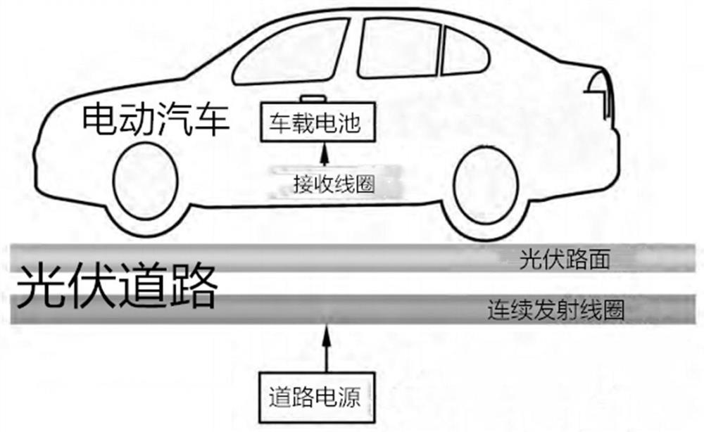
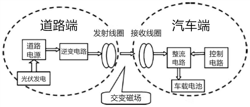
[0032] Such as figure 1 As shown, the method adopted in the present invention is to lay a continuous transmitting coil in the same direction as the road direction under the photovoltaic power generation module of the road, and reach a certain length requirement so as to form a special charging lane for a certain distance without affecting other roads. Under normal vehicle traffic conditions, electric vehicles can drive into this lane for charging. When the electric vehicle drives into the dedicated charging lane, the transmitting coil at the road end and the receiving coil at the vehicle end perform wireless transmission of electric energy through magnetic coupling, so as to achieve the purpose of using the electricity generated by the photo...


PUM


Abstract

The invention discloses a dynamic wireless charging method and device for an electric vehicle on a photovoltaic road. The device comprises a photovoltaic road power generation system and a double-layer staggered coil. Electric energy generated by the power generation system is transmitted to a running vehicle through the magnetic coupling coil. A magnetic coupling resonance type wireless chargingtechnology is adopted, a plurality of transmitting coils and receiving coils with the same resonance frequency are used for generating resonance at a specific power supply frequency, and transmissionof wireless electric energy within a distance allowable range is achieved in a magnetic coupling resonance mode. Specifically, a transmitting coil is laid under a photovoltaic road surface, current isconverted into a magnetic field through the transmitting coil, a receiving coil is installed on avehicle chassis part, and energy transmission is conducted through resonance generated when the electromagnetic frequency of the transmitting coil is the same as that of the receiving coil. The pressure of the electric vehicle charging pile is relieved, the electric vehicle can have a longer endurancemileage under the condition that the driving time is not shortened, and meanwhile charging of the electric vehicle is safer.

Description

technical field [0001] The invention belongs to the field of electric vehicle charging, and specifically relates to a wireless charging method and device for an electric vehicle, which can allow the electric vehicle to be charged while driving. Background technique [0002] In recent years, with the continuous updating and development of electric vehicles, electric vehicles have become more common in our lives. But the problem also comes with it, and that is the problem of charging electric vehicles. The current driving range of electric vehicles is mostly unsatisfactory, and the distribution and quantity of charging piles in cities and the convenience of use also greatly limit the convenience of electric vehicle charging, and at the same time, the long charging time cannot make electric vehicles as traditional. The mileage of fuel vehicles is updated so quickly, and the incident of spontaneous combustion of some electric vehicles while charging is also shocking. Therefore...

Claims


Application Information

Patent Timeline
Patent Type & Authority Applications(China)
IPC IPC(8): B60L53/12B60L53/51H02J50/12
CPCB60L53/12B60L53/51H02J50/12Y02T10/70Y02T10/7072Y02T90/12Y02T90/14
Inventor 袁朝春夏林何友国张厚忠孙晓强蔡英凤
Owner JIANGSU UNIV
Learn More