
Brake linkage system

A brake linkage and linkage technology, applied in the field of brake systems, can solve problems such as the inability to stop the vehicle

Inactive Publication Date: 2020-10-02
MING HORNG IND
View PDF7 Cites 0 Cited by
  • Summary
  • Abstract
  • Description
  • Claims
  • Application Information

AI Technical Summary

Problems solved by technology

[0004] However, since the effect of the vehicle's inertial forward movement will become more and more obvious with the increase of the braking force of the whole vehicle, if only a fixed ratio of braking force is applied to the front and rear wheels, it will not be possible to make the vehicle move smoothly stopped
Moreover, the linkage between the braking force of the front wheel and the braking force of the rear wheel cannot avoid the improper operation of the user, resulting in early deadlock of the front wheel or excessive initial braking force, which will cause the vehicle to shift or fall during the braking process.

Method used


Image

  • Brake linkage system
  • Brake linkage system
  • Brake linkage system

Examples


Embodiment Construction

[0075] Some typical embodiments embodying the features and advantages of the present invention will be described in detail in the description in the following paragraphs. It should be understood that the invention is capable of various changes in different ways without departing from the scope of the invention, and that the description and drawings therein are illustrative in nature and not intended to limit the invention. invention.

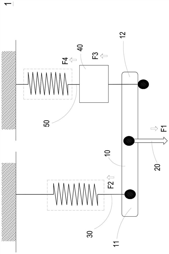
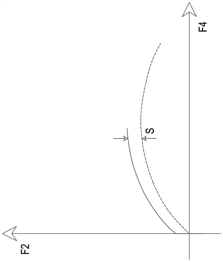
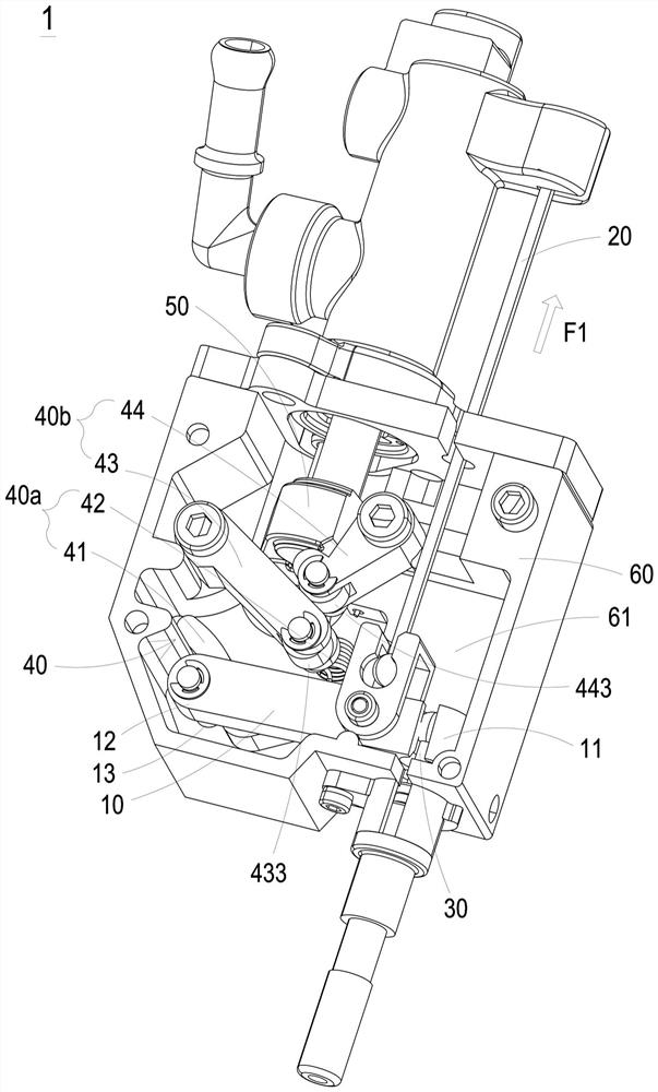
[0076] figure 1 A schematic diagram of the force action of the brake linkage system of the first preferred embodiment of the present invention is disclosed. figure 2 A relationship diagram between the first output force and the second output force in the brake linkage system of the first preferred embodiment of the present invention is disclosed. In this embodiment, the brake linkage system 1 includes a swing arm 10 , an input component 20 , a first output component 30 , a lever ratio adjusting mechanism 40 and a second output component 50 . ...


PUM


Abstract

The invention provides a brake linkage system. The brake linkage system structurally comprises a swing arm, a force input assembly, a first force output assembly, a lever ratio modulation mechanism and a second force output assembly. The swing arm has a first end and a second end opposite to each other. The force input assembly is in pin connection between the first end and the second end of the swing arm. When the force input assembly provides an input force, the swing arm generates displacement along the direction of the input force. The first output assembly at the first end generates a first output force corresponding to the input force. The lever ratio modulation mechanism is slidably connected to the second end and generates a modulation force corresponding to the input force, so that the first end and the second end swing relatively. The second force output assembly is slidably connected to the lever ratio modulation mechanism and generates a second output force in response to the input force, the first output force and the modulation force, and the second output force and the first output force are in a non-linear relationship.

Description

technical field [0001] The present invention relates to a braking system, in particular to a braking interlocking system integrating the braking force of the front wheel and the braking force of the rear wheel. Background technique [0002] The braking system is a braking system that slows down or stops a vehicle from moving forward, and stops by slowing down the rotation of the vehicle's wheels. Traditional two-wheeled vehicles are limited by the movement of the two wheels. Once an inadvertent action occurs during the braking process, in addition to greatly extending the braking distance, it is more likely to cause the tires to slide due to complete deadlock, which will further damage the body. The accident of dumping due to loss of balance seriously endangers the safety of the vehicle. [0003] In order to enhance the safety of the vehicle and prevent vehicle users from improperly operating the front and rear wheel brake systems, the current market has a brake system that...

Claims


Application Information

Patent Timeline
IPC IPC(8): B62L3/02B62L3/08B62L1/00
CPCB62L1/005B62L3/026B62L3/08
Inventor 曾全佑吴柏廷林苑婷萧富成
Owner MING HORNG IND
Learn More