Wire box automatic unloading device

A technology of automatic blanking and wire boxes, applied in the direction of transportation and packaging, conveyor objects, conveyors, etc., can solve the problems of time-consuming and labor-intensive, and achieve the effect of good conveying accuracy

Active Publication Date: 2021-11-23
浙江中财管道科技股份有限公司
View PDF7 Cites 0 Cited by
  • Summary
  • Abstract
  • Description
  • Claims
  • Application Information

AI Technical Summary

Problems solved by technology

[0003] The purpose of the present invention is to overcome the time-consuming and labor-intensive shortcomings of the prior art, and propose an automatic wire box unloading device, which saves time and effort

Method used


Image

  • Wire box automatic unloading device
  • Wire box automatic unloading device
  • Wire box automatic unloading device

Examples


Embodiment

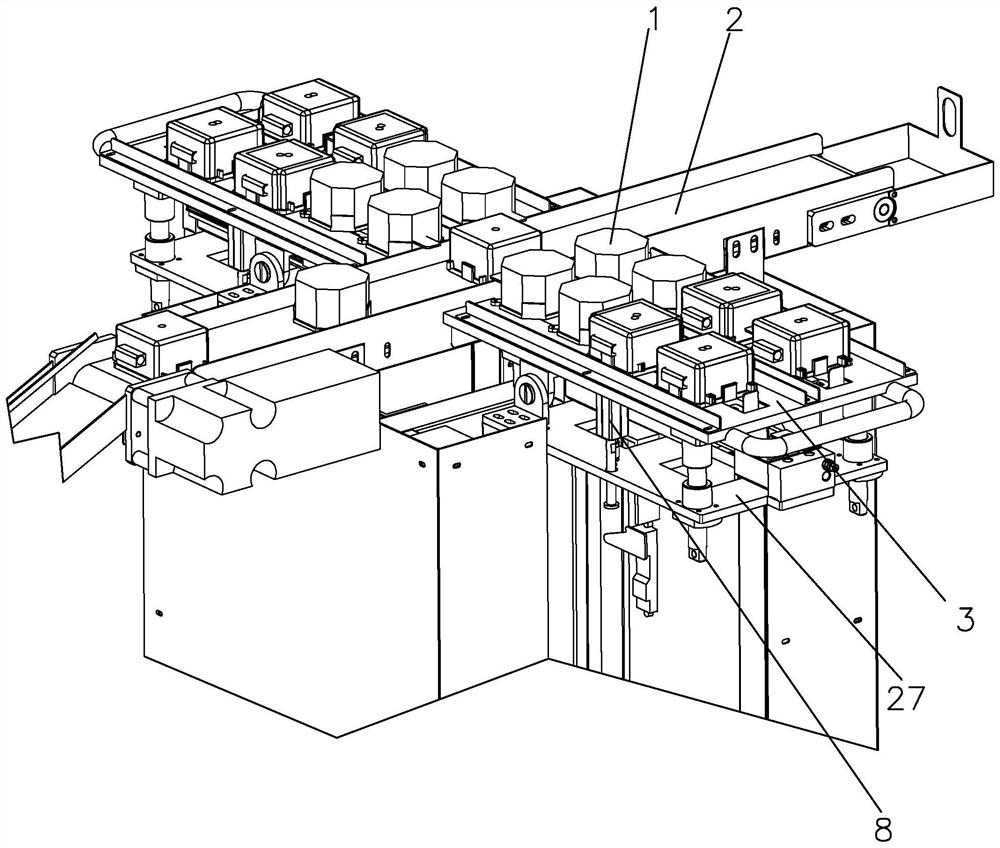
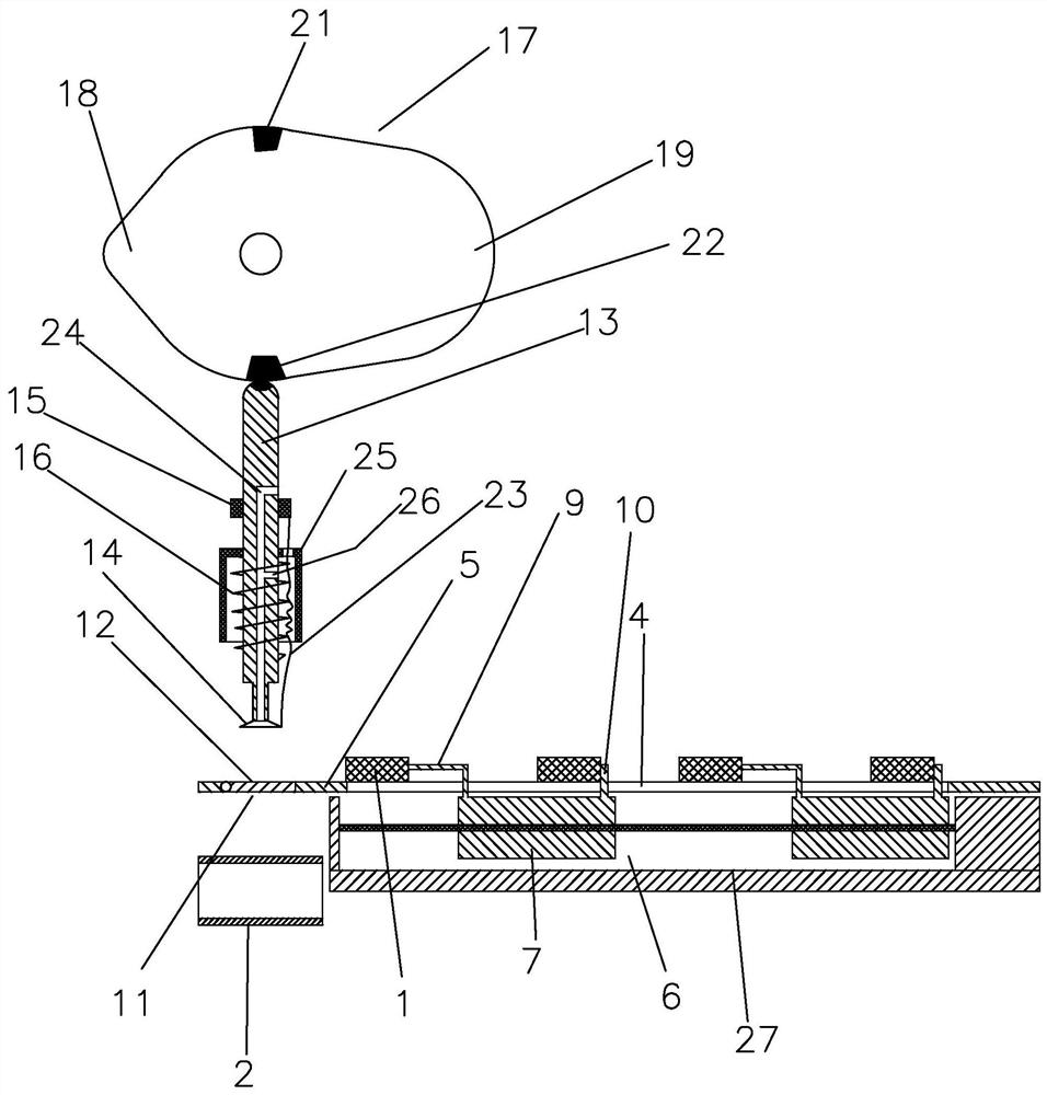
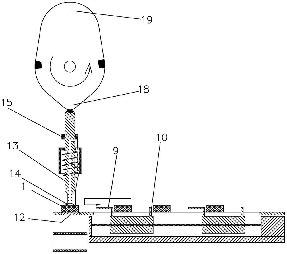
[0025] see Figure 1 to Figure 7 , an automatic wire box unloading device, comprising a conveyor belt 2 for delivering the wire box 1 to a stamping system, and a conveying mechanism for delivering the wire box 1 to the conveyor belt 2 .

[0026] The conveying mechanism includes a slide plate 3 that slides for the wire box 1 and one end is located above the conveying mechanism, a discharge port 11 located at the end of the slide block 5 close to the conveyor belt 2, a material blocking plate 12 that is connected to the discharge port 11 side in rotation, and is used for rotating The motor of the baffle plate 12, the long hole 4 arranged along the direction of the slide plate 3 on the slide plate 3, the servo module 6 including the slide block 7 under the slide block 5, and the lifting cylinder for lifting the servo module 6 8. The first push plate 9 fixed on the slider 5 is used to push the wire box 1 towards the baffle plate 12, and the first push plate fixed on the slider 5 i...


PUM


Abstract

The invention discloses an automatic wire box unloading device, which relates to the technical field of assembly line processing; it includes a conveyor belt and a conveying mechanism; The feed port of the feed port, the baffle plate connected to the side of the feed port, the motor used to rotate the baffle plate, the long holes arranged along the direction of the slide plate on the slide plate, the servo drive including the slide block located below the slide block The module, the lifting cylinder for lifting the servo module, the first push plate fixed on the slider for pushing the wire box to move toward the material stopper, the first push plate fixed on the slider for pushing another wire box The second push plate moving towards the first push plate is used to grab the wire box and place the wire box on the conveyor belt after passing down the discharge port; the slide plate is fixed above the conveyor belt, and the first The first push plate and the second push plate are slidably connected in the long hole.

Description

technical field [0001] The invention belongs to the technical field of assembly line processing, and in particular relates to an automatic unloading device for wire boxes. Background technique [0002] At present, the wire boxes need to be input to the stamping system for stamping after injection molding. At present, the wire boxes are often placed on the conveyor belt manually, and then transported to the stamping system for stamping under the action of the conveyor belt. Time-consuming. Contents of the invention [0003] The object of the present invention is to propose an automatic wire box unloading device, which saves time and labor, in order to overcome the time-consuming and labor-intensive shortcomings of the prior art. [0004] In order to achieve the above object, the present invention adopts the following technical solutions: [0005] An automatic unloading device for wire boxes, comprising a conveyor belt for conveying the wire boxes to a stamping system, and...

Claims


Application Information

Patent Timeline
Patent Type & Authority Patents(China)
IPC IPC(8): B65G47/91B65G47/82
CPCB65G47/82B65G47/912B65G2201/025
Inventor 金琥何大伟其他发明人请求不公开姓名
Owner 浙江中财管道科技股份有限公司
Why Eureka
Try Eureka