Method for activating volume control valves

A technology for controlling valves and triggering signals, applied in engine control, electrical control, fuel injection control, etc., to achieve the effect of reducing radiation and low cost

Active Publication Date: 2016-08-17
ROBERT BOSCH GMBH
View PDF9 Cites 0 Cited by
  • Summary
  • Abstract
  • Description
  • Claims
  • Application Information

AI Technical Summary

Problems solved by technology

However, as is known in the prior art, it is not possible to determine two characteristic variables independently of each other with only one measurement

Method used


Image

  • Method for activating volume control valves
  • Method for activating volume control valves
  • Method for activating volume control valves

Examples


Embodiment Construction

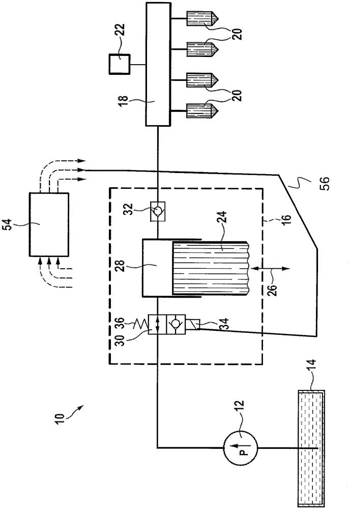
[0028] Fuel injection system in figure 1 Zhong has the reference number 10 as a whole. The fuel injection system includes an electric fuel pump 12, and the fuel pump 12 delivers fuel from a fuel tank 14 to a high-pressure pump 16. The high-pressure pump 16 compresses the fuel to a high pressure and delivers it further into the fuel rail 18. A plurality of injectors 20 are connected to the fuel rail 18, and the injectors 20 inject fuel into the combustion chambers allocated to it. The pressure in the fuel rail 18 is detected by a pressure sensor 22.

[0029] The high-pressure pump 16 is, for example, a piston pump with a delivery piston 24 which can be placed in reciprocating motion by a camshaft (not shown) (double arrow 26). The delivery piston 24 defines a delivery chamber 28, and the delivery chamber 28 can be connected to the outlet of the electric fuel pump 12 via a quantity control valve 30. In addition, the delivery chamber 28 may be connected to the fuel rail 18 throug...


PUM


Abstract

In a method for controlling a quantity control valve, at least two parameters characterizing the quantity control valve are utilized. A control signal supplied to the quantity control valve is defined by the at least two parameters. At least one parameter is ascertained based on the result of a first adaptation and a second adaptation, or based on the result of a first adaptation and the other parameter.

Description

Technical field [0001] The invention relates to a method for an operating volume control valve. In addition, a computer program, an electrical storage medium and a control and adjustment device are the subject of the present invention. The invention can be used in particular in a fuel injection system of an internal combustion engine, wherein the fuel injection system includes a high-pressure pump. For example, a quantity control valve for inputting fuel is allocated to the high-pressure pump, wherein the quantity control valve controls the quantity of fuel delivered by the high-pressure pump. The quantity control valve is provided, for example, with a magnetic valve that can be operated electromagnetically by a coil. Background technique [0002] DE 10 2007 035 316 discloses a method for triggering a quantity control valve with a solenoid valve that can be electromagnetically actuated by a coil, for which a first current value is applied to the solenoid valve The coil is ener...

Claims


Application Information

Patent Timeline
Patent Type & Authority Patents(China)
IPC IPC(8): F02D41/24F02D41/20
CPCF02D41/2464F02D41/20F02D41/2467F02D41/248F02D41/3845F02D2041/2027F02D2041/2051F02D2041/2058F02D2200/0602F02M59/366F02M63/0225
Inventor R.威尔姆斯M.舒马歇J.金佩尔M.梅斯
Owner ROBERT BOSCH GMBH
Why Eureka
Try Eureka