
Positioning device for automatic feeding of metal tensile test robot, and feeding method

A tensile test and automatic feeding technology, which is applied in the direction of measuring devices, using stable tension/pressure testing material strength, instruments, etc., to achieve the effects of reducing manual labor intensity, simple and reliable mechanism, and improving production efficiency

Pending Publication Date: 2020-10-02
TSINGHUA UNIV TIANJIN HIGH END EQUIP RES INST LUOYANG ADVANCED MFG IND RES & DEV BASE
View PDF0 Cites 1 Cited by
  • Summary
  • Abstract
  • Description
  • Claims
  • Application Information

AI Technical Summary

Problems solved by technology

[0004] The purpose of the present invention is to provide a metal tensile test robot automatic feeding positioning device, which solves the problem of the robot automatically feeding the stretching machine, and realizes the purpose of automatic production of the metal tensile test

Method used


Image

  • Positioning device for automatic feeding of metal tensile test robot, and feeding method
  • Positioning device for automatic feeding of metal tensile test robot, and feeding method

Examples


Embodiment Construction

[0027] In order to further explain the technical means and effects of the present invention to achieve the intended purpose of the invention, the specific implementation of the positioning device for automatic feeding of the metal tensile test robot proposed according to the present invention will be described below in conjunction with the accompanying drawings and preferred embodiments. , structure, feature and effect thereof, detailed description is as follows.

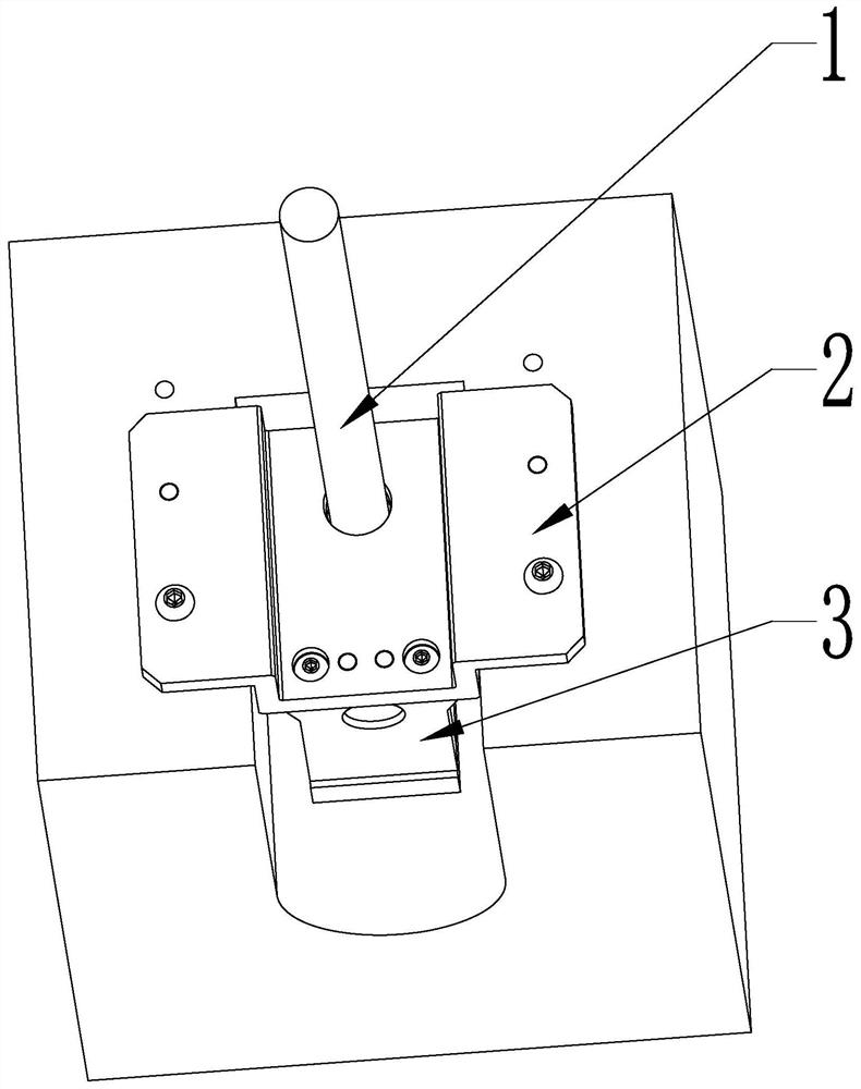
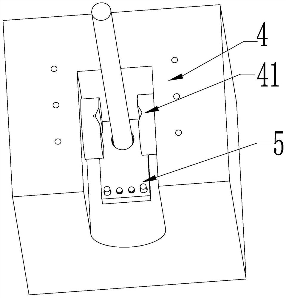
[0028] see figure 1 with figure 2 , which is a structural schematic diagram of a positioning device for automatic feeding of a metal tensile test robot in the present invention, the positioning device includes a clamp 4, and the positioning base 5 at the bottom of the clamping cavity of the clamp 4 is provided with a bar for the lower end of the rod 1 to extend into. The first guide hole with the upper end open and the lower end closed to realize the positioning of the lower end of the bar, the positioning plate 2...


PUM


Abstract

The invention relates to a positioning device for automatic feeding of a metal tensile test robot, and a feeding method using the positioning device. The positioning device comprises a clamp, and a positioning bottom plate at the bottom of a clamping cavity of the clamp is provided with a first guide hole for allowing the lower end of a bar to extend into to realize positioning of the lower end ofthe bar; and a positioning plate fixedly arranged on the upper surface of the clamp is provided with a second guide hole which is coaxial with the first guide hole and used for allowing the bar to penetrate into the center of the clamping portion of the clamp and achieving positioning of the upper end of the bar, and the positioning device is further provided with a center hole used for calibrating the relative position of the robot and a stretcher. The positioning device is simple and reliable in mechanism and capable of meeting the actual production requirement while manual participation isavoided. By using the positioning device, the bottleneck of automatic feeding of the metal tensile test robot is solved, and coarse positioning is provided for robot feeding, so the production efficiency is greatly improved, and the labor intensity of workers is reduced.

Description

technical field [0001] The invention belongs to the field of automatic feeding of metal tensile test robots, and relates to a positioning device, in particular to a robot automatic feeding positioning device and a feeding method. Background technique [0002] The positioning device is the main component of the automatic feeding system of the metal tensile test robot. At present, during the metal tensile test process, through manual operation, the right hand first supports the bar into a vertical state, and then puts the bar on the metal tensile test. Test the clamp center of the tensile machine, visually inspect the height direction to ensure the clamping amount of the tensile machine clamp, operate the hydraulic clamp hand-held box button with the left hand, and operate the button to clamp the clamp to complete the loading of the metal tensile test tensile machine. This manual operation method requires the coordination of left and right hands to operate, and the right hand ...

Claims


Application Information

Patent Timeline
IPC IPC(8): G01N3/04G01N3/08B65G47/90
CPCB65G47/90G01N3/04G01N3/08G01N2203/0405
Inventor 吴哲明刘佳君刘媛君邓岩李纪涛马明星鲁志敏
Owner TSINGHUA UNIV TIANJIN HIGH END EQUIP RES INST LUOYANG ADVANCED MFG IND RES & DEV BASE
Learn More