
An electronically controlled rain-proof surveillance camera

An electronically controlled, camera technology, applied in the field of electronically controlled rain-proof surveillance cameras, can solve the problems of affecting the service life, the invasion of moisture and dust, and speed up the aging speed of internal components, so as to maintain normal work and speed up The effect of ventilation rate

Active Publication Date: 2021-09-03
浙江优绣家居用品有限公司
View PDF7 Cites 0 Cited by
  • Summary
  • Abstract
  • Description
  • Claims
  • Application Information

AI Technical Summary

Problems solved by technology

[0003] An electronically controlled rainproof monitoring camera proposed by the present invention aims to solve the problem that the monitoring device in the traditional technology is continuously connected with the outside during the heat dissipation process, which is easily attacked by moisture and dust in the environment, and accelerates the aging speed of internal components. Problems affecting its service life

Method used


Image

  • An electronically controlled rain-proof surveillance camera
  • An electronically controlled rain-proof surveillance camera
  • An electronically controlled rain-proof surveillance camera

Examples


Embodiment Construction

[0022] The following will clearly and completely describe the technical solutions in the embodiments of the present invention with reference to the accompanying drawings in the embodiments of the present invention. Obviously, the described embodiments are only some, not all, embodiments of the present invention.

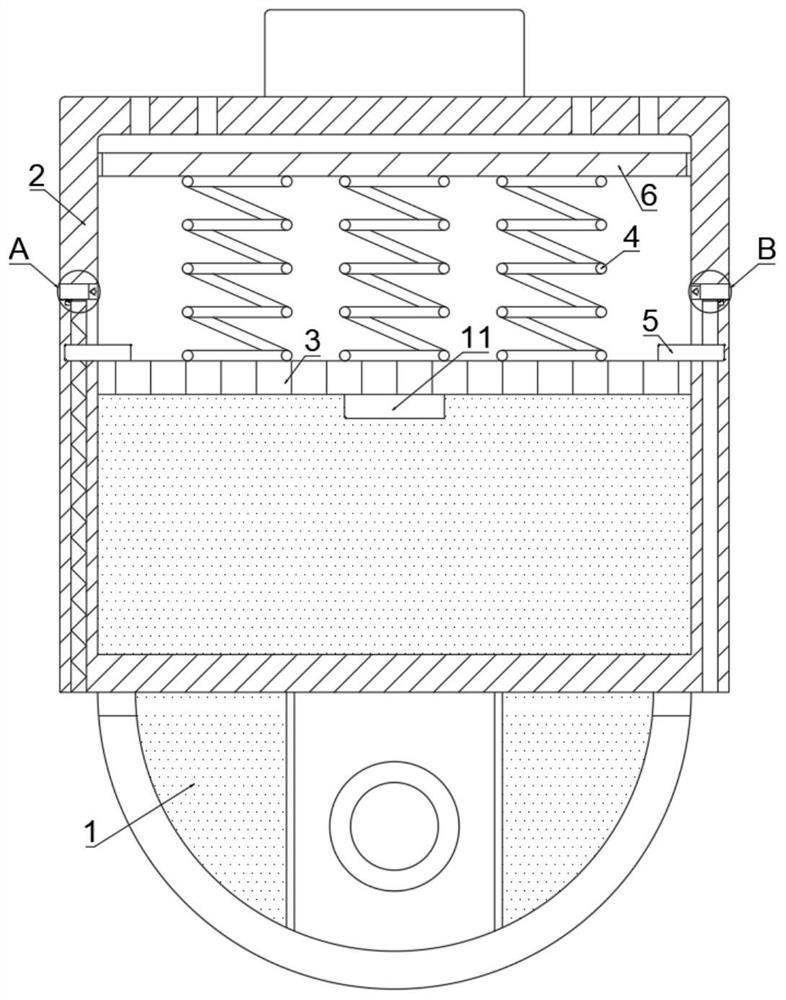
[0023] refer to Figure 1-5 , an electronically controlled rainproof monitoring camera, comprising a monitoring body 1 and a protective cover 2, the monitoring body 1 is installed on the bottom of the protective cover 2, and the outer side of the protective cover 2 away from the monitoring body 1 is installed on the monitoring rod, and the protective cover 2 is Cylindrical, the monitoring body 1 extends out of the protective cover 2 and the bottom is hemispherical, and the input end of the internal shooting device points to one side.

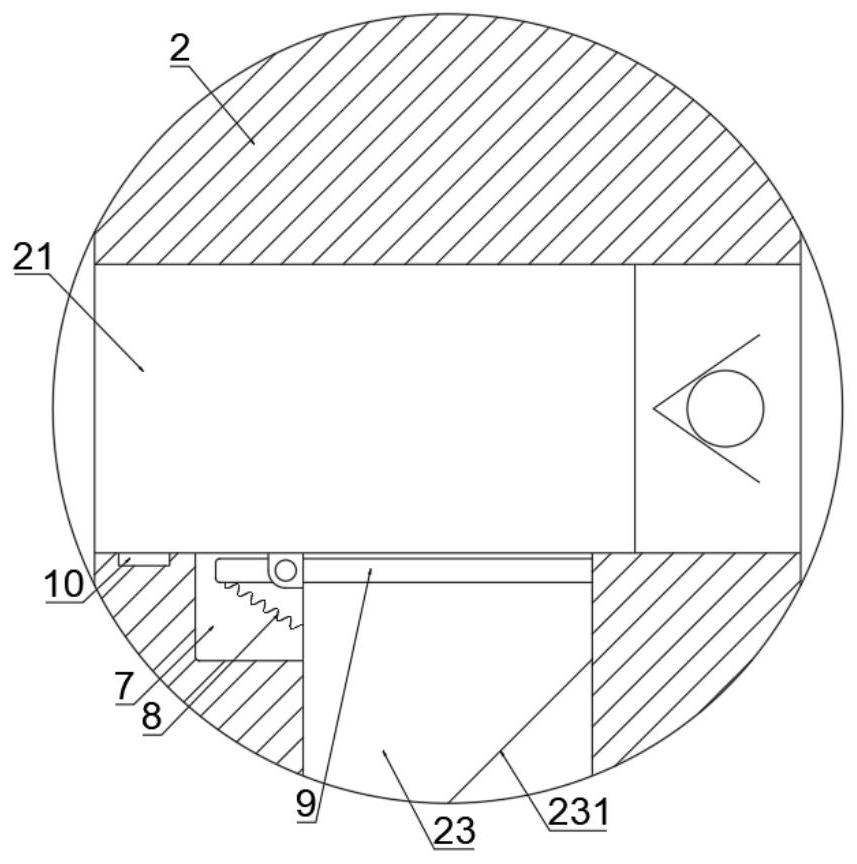
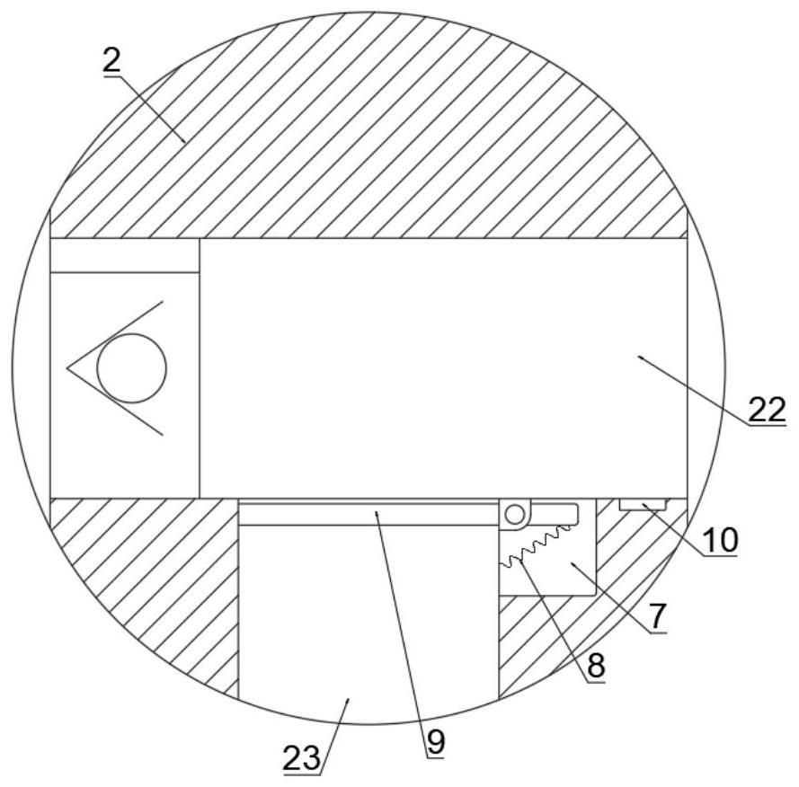
[0024] A heat conduction plate 3 is fixedly connected to the protective cover 2 , and one side of the heat conduction plate 3 is conn...


PUM


Abstract

The invention discloses an electronically controlled rainproof monitoring camera, which relates to the technical field of monitoring devices and comprises a monitoring body and a protective cover. The monitoring body is installed at the bottom of the protective cover, and the protective cover is installed on the monitoring On the rod, a heat conduction plate is fixedly connected in the protective cover, one side of the heat conduction plate is connected to the monitoring body through heat conduction, and a plurality of conductive springs and power generation sheets are fixedly connected to the side of the heat conduction plate away from the monitoring body. The output end of the chip is electrically connected with a controller, and the controller is installed in the protective cover and electrically connected with a plurality of conductive springs. In the present invention, in sunny days, the monitoring body gradually generates heat during the continuous working process, so that the inside of the protective cover When the temperature rises, the controller cooperates with the thermoelectric generator to output pulse current to multiple conductive springs, and the conductive springs pull the sliding plate to move back and forth in the protective cover, so as to quickly discharge the hot air in the protective cover for direct heat dissipation.

Description

technical field [0001] The invention relates to the technical field of monitoring devices, in particular to an electronically controlled rainproof monitoring camera. Background technique [0002] In urban monitoring and management, a monitoring network is generally formed through monitoring cameras on the road, so as to collect corresponding monitoring data and assist in urban security management. Since the monitoring device is directly exposed to the external environment, and in the long-term working process, more heat will be gradually generated inside the monitoring device. In order to maintain the normal operation of the monitoring device, it is necessary to dissipate heat from the monitoring device. During the continuous communication with the outside world, it is vulnerable to moisture and dust in the environment, which accelerates the aging rate of internal components, affects its service life, and then affects the working effect of surveillance cameras. Contents of...

Claims


Application Information

Patent Timeline
Patent Type & Authority Patents(China)
IPC IPC(8): G03B17/55G03B17/08H04N5/225
CPCG03B17/55G03B17/08H04N23/52H04N23/51
Inventor 李明
Owner 浙江优绣家居用品有限公司
Learn More