Remote sensing image change detection method and device

A change detection and remote sensing image technology, applied in the field of image processing, can solve the problems of manual inspection, failure to improve operation efficiency, and difficulty in meeting surveying and mapping production, and achieve the effect of improving detection efficiency and speed

Pending Publication Date: 2020-10-02
中国国土勘测规划院
View PDF2 Cites 8 Cited by
  • Summary
  • Abstract
  • Description
  • Claims
  • Application Information

AI Technical Summary

Problems solved by technology

However, once a missed detection occurs, it is necessary to manually check the images of the remaining 95% of the patches from scratch
Therefore, for the automatic change detection algorithm, once the missed detection rate does not meet the requirements, the result will be difficult to meet the requirements of surveying and mapping production, and manual inspection is required
From this perspective, the results of automated extraction cannot improve any operational efficiency
[0003] Therefore, due to the particularity of the change detection business, when most other surveying and mapping products (DOM, DEM, DSM, etc.) Visual interpretation and extraction, existing computer automatic algorithms and tools cannot meet the high-precision change detection requirements for surveying and mapping production

Method used


Image

  • Remote sensing image change detection method and device
  • Remote sensing image change detection method and device
  • Remote sensing image change detection method and device

Examples


Embodiment Construction

[0024] The following will clearly and completely describe the technical solutions in the embodiments of the present invention with reference to the accompanying drawings in the embodiments of the present invention. Obviously, the described embodiments are only some, not all, embodiments of the present invention. Based on the embodiments of the present invention, all other embodiments obtained by persons of ordinary skill in the art without making creative efforts belong to the protection scope of the present invention.

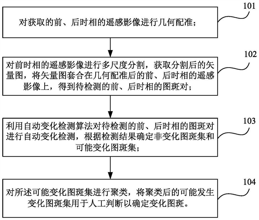
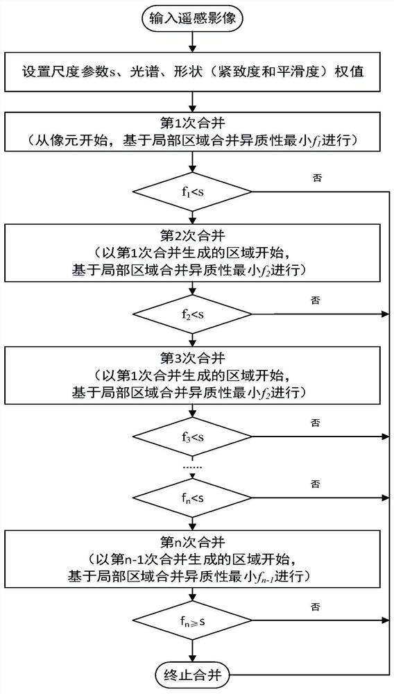
[0025] Based on the research and analysis of the advantages and disadvantages of the existing computer automatic extraction of change information and manual manual extraction of change information, the present invention proposes a strategy for high-resolution remote sensing image change detection oriented to surveying and mapping production, which is mainly divided into the following three steps : 1) Multi-scale segmentation of remote sensing images. Firstly, g...


PUM


Abstract

The embodiment of the invention provides a remote sensing image change detection method and device, and the method comprises the steps of carrying out the geometric registration of an obtained remotesensing image of a front time phase and an obtained remote sensing image of a rear time phase; carrying out multi-scale segmentation on the remote sensing image of the front time phase to obtain a segmented vector diagram, and nesting the vector diagram on the geometrically registered remote sensing image of the front time phase and the geometrically registered remote sensing image of the rear time phase to obtain a to-be-detected pattern spot pair of the front time phase and the rear time phase; utilizing an automatic change detection algorithm to carry out automatic change detection on the pattern spot pairs of the front and rear time phases to be detected, and determining a non-change pattern spot set and a possible change pattern spot set according to a detection result; and clusteringthe possible change pattern spot set, and applying the clustered possible change pattern spot set to manual judgment to determine a change pattern spot. According to the technical scheme, the efficiency of manually extracting change information in surveying and mapping production can be improved.

Description

technical field [0001] The invention relates to the field of image processing, in particular to a remote sensing image change detection method and device. Background technique [0002] With the development of earth observation technology and the continuous improvement of the resolution of remote sensing images, extracting ground object information from remote sensing images has become a very important direction. Land resource management and planning, environmental protection, surveying and mapping geographic information, etc. all require rapid and accurate monitoring of these land cover changes. There are mainly two types of extraction methods for change detection of remote sensing images: 1) Completely manual extraction. Experienced change monitoring operators superimpose the front and rear remote sensing images of the two scenes, and use tools such as rolling shutters to judge the images line by line. Tuban carefully checked. Under normal circumstances, it has the highes...

Claims


Application Information

Patent Timeline
Patent Type & Authority Applications(China)
IPC IPC(8): G06T7/30G06T7/10G06K9/62
CPCG06T7/30G06T7/10G06T2207/30181G06F18/23213
Inventor 郭旭东余凡鲁学军陈瑜琦张智杰
Owner 中国国土勘测规划院
Why Eureka
Try Eureka