Voltage-adaptive constant-current circuit, calibration device and calibration method

A technology of self-adaptive voltage and constant current circuit, which is applied in the testing of measuring devices, electrical components, machines/structural components, etc. It can solve the problems of current controller burnout, low efficiency, heat generation, etc., to reduce heat loss and work efficiency High and cost-reducing effects

Active Publication Date: 2020-10-02
WUHAN JINGLI ELECTRONICS TECH +1
View PDF7 Cites 0 Cited by
  • Summary
  • Abstract
  • Description
  • Claims
  • Application Information

AI Technical Summary

Problems solved by technology

[0011] 1. The structure of the built constant current drive circuit is simple, usually only applicable to a narrow range of rated voltage;
[0012] 2. The voltage at both ends of the current controller will be changed by the rated voltage of the connected LED light source, resulting in severe heating, which further reduces the working efficiency of the entire circuit, and even burns out the current controller;
[0013] 3. Before each calibration work, the preparation time is required in the early stage, and the calibration can only be performed after stabilization, which takes a long time and is inefficient;
[0014] 4. Additional heat dissipation and temperature control equipment are required, resulting in high costs

Method used


Image

  • Voltage-adaptive constant-current circuit, calibration device and calibration method
  • Voltage-adaptive constant-current circuit, calibration device and calibration method
  • Voltage-adaptive constant-current circuit, calibration device and calibration method

Examples


Embodiment Construction

[0060] Below in conjunction with specific embodiment, further illustrate the present invention, should be understood that these embodiments are only used to illustrate the present invention and are not intended to limit the scope of the present invention, after having read the present invention, those skilled in the art will understand various equivalent forms of the present invention All modifications fall within the scope defined by the appended claims of the present application.

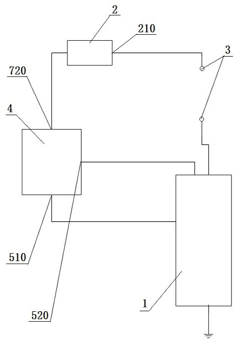
[0061] The specific embodiment of the present invention is based on such as figure 1 An adaptive voltage constant current circuit is shown, including.

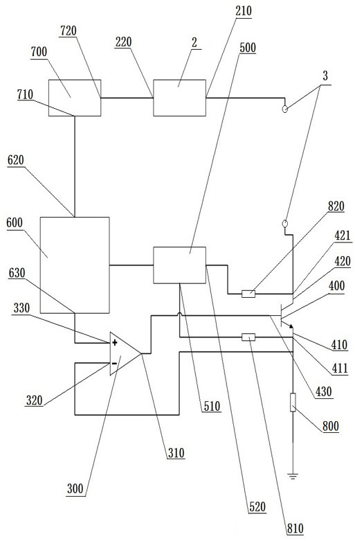
[0062] Constant current source module 1: used to provide constant current for the electrical equipment connected to the constant current circuit; the constant current source module 1 includes a current controller 400 for controlling the current passing through the electrical equipment; the current source module 1 also includes The voltage dividin...


PUM


Abstract

The invention relates to a voltage-adaptive constant-current circuit, which comprises a constant-current source module, a voltage source module, a power supply interface and a feedback adjustment module, wherein the constant current source module comprises a current controller and a divided resistor, the power supply interface comprises a first terminal and a second terminal, and the feedback adjustment module comprises a first voltage acquisition port, a second voltage acquisition port and an analog signal output end. The invention further relates to a Flicker tester calibration device for driving a LED light source to work by using the constant-current circuit. The invention also relates to a method for calibrating by using the Flicker tester calibration device, wherein the method comprises the following steps of: inserting a LED light source; adjusting the voltages at the two ends of the LED light source to be rated voltages in real time; controlling the LED light source to flicker;collecting a first voltage and a second voltage of a current controller, and calculating voltages at two ends; adjusting voltages at two ends in real time; and aligning a Flicker tester with the LED,and calibrating. According to the invention, heat dissipation and temperature control equipment does not need to be additionally arranged, so that the cost is low; rated voltages of all LEDs are basically compatible, so that universality is good; the heating loss can be reduced; and work efficiency is high.

Description

technical field [0001] The invention relates to the technical field of panel detection, in particular to an adaptive voltage constant current circuit and a calibration device and method. Background technique [0002] In recent years, with the rapid development of LCD and OLED screens, the power of LED backlight that provides brightness to the screen is also increasing. At the same time, as users have higher and higher requirements for screen flicker, the so-called flicker quality, screen manufacturers It is also necessary to do a flicker test specifically for the screen panel and LED backlight produced. [0003] LED is a relatively special light-emitting device. When working, the rated voltage remains unchanged. If you want to change the brightness, you can only control the current of the LED. As a manufacturer of flicker testing equipment, the accuracy of the flicker testing equipment is of particular concern. It is necessary to use many light sources with different strobe...

Claims


Application Information

Patent Timeline
IPC IPC(8): H05B45/345G01M11/00
CPCG01M11/00H05B45/345
Inventor 张博佳
Owner WUHAN JINGLI ELECTRONICS TECH
Why Eureka
Try Eureka