Gate road rolling shaft type sieving, crushing and transferring device

A technology of transfer device and crushing device, which is applied in transportation and packaging, screening, solid separation, etc., can solve the problem of loss of lump coal rate and achieve the effect of increasing lump coal rate

Pending Publication Date: 2020-10-09
NINGXIA TIANDI BENNIU IND GRP +1
View PDF0 Cites 2 Cited by
  • Summary
  • Abstract
  • Description
  • Claims
  • Application Information

AI Technical Summary

Problems solved by technology

[0004] However, the scraper chain of the reloading machine is always running in a closed loop. When a small piece of raw coal falls close to the drop hole, the scraper of the scraper chain may impact the small piece of raw coal, and the small piece of raw coal will be sheared and broken , which also causes the loss of lump coal rate. Because the crusher needs to rely on the scraper chain of the reloader to transfer the large piece of raw coal and the tank of the reloader cooperates with the crusher to crush the large piece of raw coal, and the screening tank can only The screening function can only be realized if it is located between the reloader and the crusher. As a result, there must be a scraper chain passing through the right below the screening tank. Therefore, on the basis of increasing the screening function, it is necessary to prevent small pieces of raw coal from being carried out by the scraper. Secondary shear crushing is a difficult problem that needs to be solved urgently

Method used


Image

  • Gate road rolling shaft type sieving, crushing and transferring device
  • Gate road rolling shaft type sieving, crushing and transferring device
  • Gate road rolling shaft type sieving, crushing and transferring device

Examples


Embodiment Construction

[0023] In order to more clearly illustrate the technical solutions of the embodiments of the present invention, the following will briefly introduce the accompanying drawings that need to be used in the embodiments. Obviously, the accompanying drawings in the following description are some embodiments of the present invention. Ordinary technicians can also obtain other drawings based on these drawings on the premise of not paying creative work.

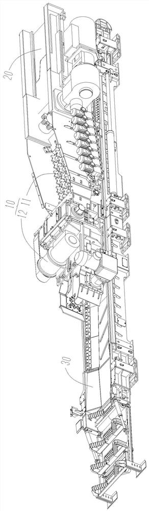
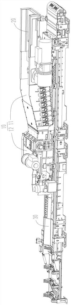
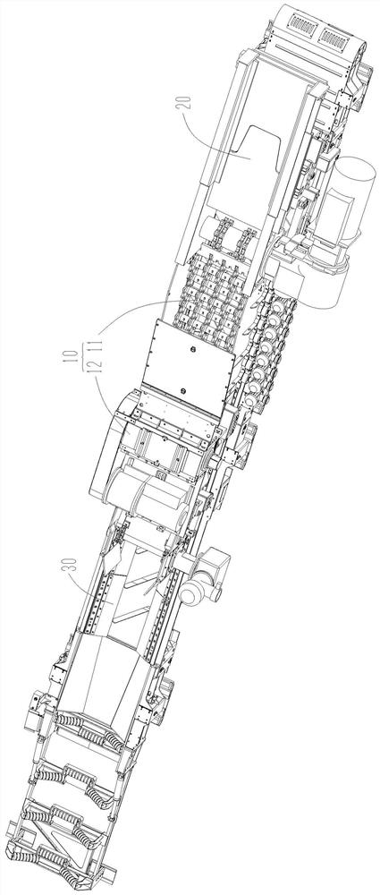
[0024] Please see Figure 1 to Figure 3 and Image 6 , the embodiment of the present invention provides a 1102-type screening and crushing transfer device 10 along the groove, which is connected with the head 20 of the transfer machine and the tail 30 of the belt conveyor, including a screening device 11 and a crushing device 12, both of which are located at The tail 30 of the belt conveyor is directly above and is located at the end of the head 20 of the transfer machine. The head 20 of the transfer machine, the screening device 11 ...


PUM


Abstract

The invention provides a gate road rolling shaft type sieving, crushing and transferring device and relates to the technical field of conveying equipment for coal mine underground mining. The gate road rolling shaft type sieving, crushing and transferring device is connected with a machine head of a reversed loader and a machine tail of a belt machine. The gate road rolling shaft type sieving, crushing and transferring device comprises a sieving device and a crushing device. The sieving device and the crushing device are located right above the machine tail of the belt machine and located on the end portion of the machine head of the reversed loader. The machine head of the reversed loader, the sieving device and the crushing device are sequentially connected. The crushing device comprisesa scraping plate chain assembly, a gate body and a scraping plate chain power portion. The crushing device is provided with a transferring mechanism. Raw coal is autonomously transferred and crushedthrough the crushing device. The sieving device is directly arranged right above the machine tail of the belt machine. Small patches of raw coal obtained after sieving directly pass through the sieving device and fall on the machine tail of the belt machine to be conveyed away without passing through the reversed loader longitudinally. A scraping plate of the reversed loader does not touch the small patches of raw coal obtained after sieving completely. The situation that the small patches of raw coal is shorn and crushed for a second time is avoided. While having a sieving function, the lumpcoal rate can be improved relatively.

Description

technical field [0001] The invention relates to the technical field of coal mine mining and conveying equipment, in particular to a trough-roller type screening, crushing and transporting device. Background technique [0002] After the raw coal is mined, it is unloaded by the scraper conveyor to the reloader with a crusher for crushing and transshipment, and then unloaded to the belt conveyor. Because the mined raw coal is of different sizes, all the raw coal is crushed by the crusher without being screened and separated. While the raw coal is crushed, some small pieces of raw coal are also crushed into fine coal by the crusher, resulting in a great reduction in the lump coal rate. [0003] According to the above problems, in order to increase the lump coal rate, some coal enterprises have improved the crushing and reloading machine, and added a screening trough with screening holes in the suspended section of the traditional reloading machine, and the screening trough is se...

Claims


Application Information

Patent Timeline
Patent Type & Authority Applications(China)
IPC IPC(8): B02C23/16B07B1/15B65G19/10B65G15/32
CPCB02C23/16B07B1/15B65G15/32B65G19/10
Inventor 田彬宜赵磊王春生张贵强卜侃侃高成军高文军刘金有黄尧孙永林王镇乾张庭利张鹏胡万飞
Owner NINGXIA TIANDI BENNIU IND GRP
Why Eureka
Try Eureka