

Circuit board welding gun achieving automatic feeding
An automatic feeding and circuit board technology, which is applied in the direction of tin feeding device, welding equipment, welding/welding/cutting items, etc., can solve the problems of easy blockage, feeding jam, low accuracy of tin material staining, etc., and achieve enhanced strength , Precise effect of discharging
- Summary
- Abstract
- Description
- Claims
- Application Information
AI Technical Summary
Problems solved by technology
Method used
Image

Examples
Embodiment 1
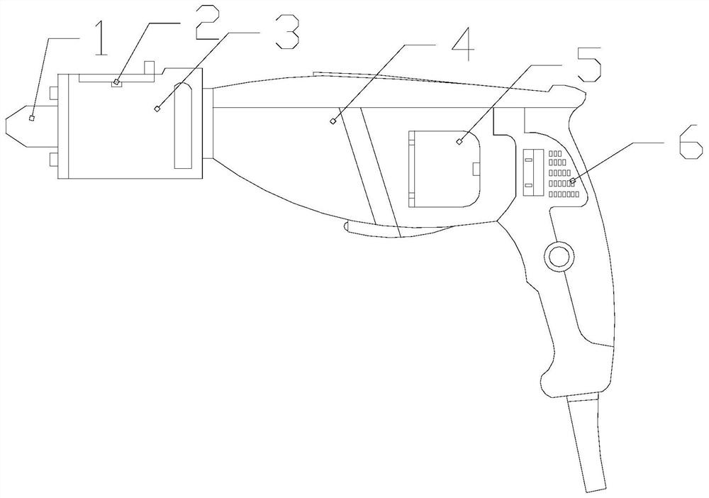
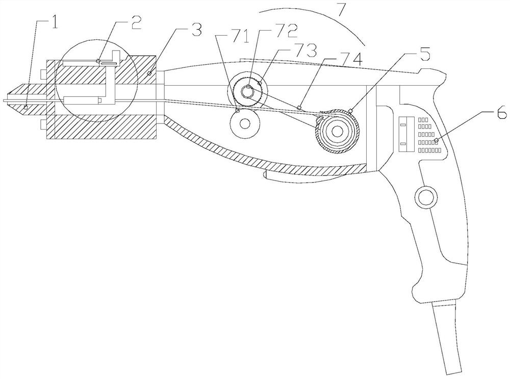
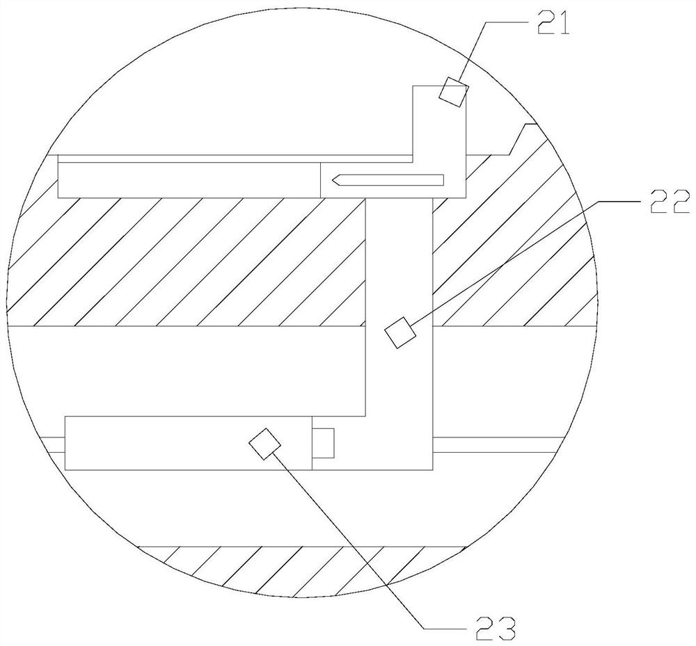
[0024] see Figure 1-Figure 5 , a circuit board welding torch for automatic feeding. The invention provides a circuit board welding gun for automatic feeding. Its structure includes a welding head 1, a wire wiping structure 2, a front end 3, a main body 4, an automatic outlet 5, and a handle 6. The horizontal ends of the main body 4 are respectively equipped with a front end 3 and a handle 6, an automatic outlet 5 is installed inside the main body 4, and an electric welding head 1 is installed at the opposite end of the front end 3 and the main body 4, so The electric welding head 1 and the wire wiping structure 2 are matched.
[0025] The automatic outlet device 5 is provided with a casing 51, a motor 52, and a rotating shaft 53. The cross section of the casing 51 is an incomplete circle, and the opening of the incomplete circle of the casing 51 is the outlet. A motor 52 is installed in the middle of the shell 51, the output shaft of the motor 52 is mechanically connected to...
Embodiment 2
[0031] see Figure 1-Figure 5 , a circuit board welding torch for automatic feeding. The invention provides a circuit board welding gun for automatic feeding. Its structure includes a welding head 1, a wire wiping structure 2, a front end 3, a main body 4, an automatic outlet 5, and a handle 6. The horizontal ends of the main body 4 are respectively equipped with a front end 3 and a handle 6, an automatic outlet 5 is installed inside the main body 4, and an electric welding head 1 is installed at the opposite end of the front end 3 and the main body 4, so The electric welding head 1 and the wire wiping structure 2 are matched.
[0032] The automatic outlet device 5 is provided with a casing 51, a motor 52, and a rotating shaft 53. The cross section of the casing 51 is an incomplete circle, and the opening of the incomplete circle of the casing 51 is the outlet. A motor 52 is installed in the middle of the shell 51, the output shaft of the motor 52 is mechanically connected to...
PUM
 Abstract
Description
Claims
Application Information