Positioning transfer jig

A fixture and transfer technology, applied in the direction of manufacturing tools, workpiece clamping devices, etc., can solve the problems of glass surface wear, low operating efficiency, and affecting the appearance of glass, and achieve the effect of accurate pick and place and improve operating efficiency

Pending Publication Date: 2020-10-09
MITAC PRECISION TECH(KUNSHAN) CORP
View PDF7 Cites 2 Cited by
  • Summary
  • Abstract
  • Description
  • Claims
  • Application Information

AI Technical Summary

Problems solved by technology

[0004] 1. The accuracy of manual placement is low and the work efficiency is low;
[0005] 2. During the pick-and-place process, it is easy to cause the glass surface to be worn and affect the appearance of the glass

Method used


Image

  • Positioning transfer jig
  • Positioning transfer jig
  • Positioning transfer jig

Examples


Embodiment Construction

[0023] The technical solutions of the present invention will be further described below in conjunction with the accompanying drawings and through specific implementation methods.

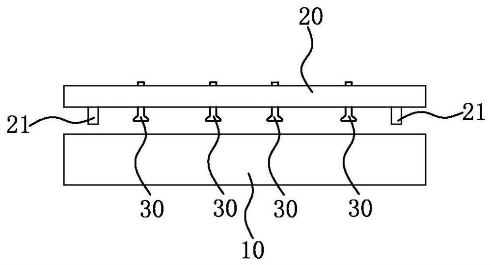
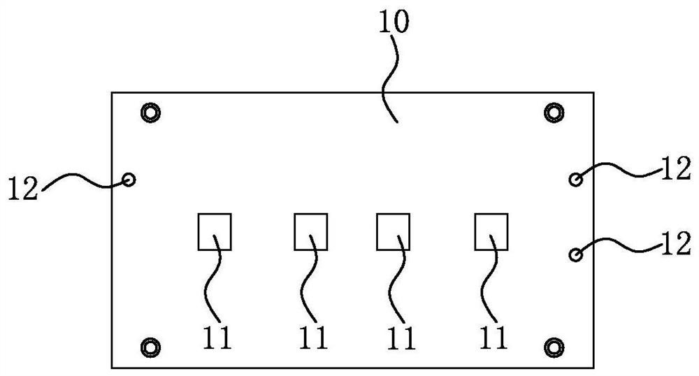
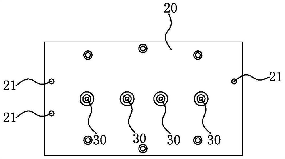
[0024] Such as Figure 1-3 As shown, a positioning transfer jig is used to pick and place workpieces in cooperation with a mechanical arm; the positioning transfer jig includes a base 10 , a connecting plate 20 and at least one set of soft suction cups 30 . Wherein, the top surface of the base 10 is provided with at least one profiling positioning groove 11; the connecting plate 20 is arranged on the top of the base 10, and is connected with the mechanical arm; the soft sucker 30 is connected to the bottom of the connecting plate 20, and a set of soft The soft suction cups 30 correspond to one profiling positioning groove 11; each group includes at least one soft suction cup 30; each soft suction cup 30 is connected with a vacuuming device.

[0025] Specifically, in the positioning and transferring...


PUM


Abstract

The invention relates to the field of automatic equipment, and particularly discloses a positioning transfer jig which is matched with a mechanical arm and used for taking and placing workpieces. Thepositioning transfer jig comprises a base, a connecting plate and at least one group of soft suckers. The top surface of the base is provided with at least one profiling positioning groove. The connecting plate is arranged above the base and connected with the mechanical arm. The soft suckers are connected to the bottom of the connecting plate, one group of the soft suckers corresponds to one profiling positioning groove, each group of soft suckers comprises at least one soft sucker, and each soft sucker is connected with a vacuumizing device. The positioning transfer jig can realize accuratetaking and placing of workpieces, avoids damaging the appearance of the workpieces in the taking and placing process, and improves the operation efficiency.

Description

【Technical field】 [0001] The invention relates to the field of automatic processing equipment, in particular to a positioning and transferring jig. 【Background technique】 [0002] With the development of electronic and electrical equipment and information equipment such as notebook computers, tablet notebooks, mobile phones, portable information terminals, and cameras, there is a strong demand for thin and lightweight products in the market. For example, the display screen of a notebook computer, in order to meet the demand for light and thin products in the market, adopts the method of glass embedded molding, that is, when molding, first put the glass into the mold, and then inject glue into the mold, so as to achieve A plastic frame is formed around the glass. [0003] Before the glass is embedded into the molding, the glass is usually put into the molding mold by a human workpiece; after the injection molding is completed, the molded part is removed manually. However, w...

Claims


Application Information

Patent Timeline
Patent Type & Authority Applications(China)
IPC IPC(8): B25B11/00
CPCB25B11/005
Inventor 林品妍李翊豪
Owner MITAC PRECISION TECH(KUNSHAN) CORP
Why Eureka
Try Eureka