Manual positioning and clamping device

A positioning clamping and floating block technology, applied in workpiece clamping devices, manufacturing tools, etc., can solve problems such as low clamping efficiency and cumbersome clamping process, and achieve improved clamping efficiency, simple clamping methods, and simple structure Effect

Active Publication Date: 2020-10-09
苏州润弘安创自动化科技有限公司
View PDF9 Cites 8 Cited by
  • Summary
  • Abstract
  • Description
  • Claims
  • Application Information

AI Technical Summary

Problems solved by technology

At present, the characteristics of incoming parts are usually used, and the parts to be processed are manually clamped to the bench vise or fixture. The clamping process is cumbersome, resulting in low clamping efficiency.

Method used


Image

  • Manual positioning and clamping device
  • Manual positioning and clamping device
  • Manual positioning and clamping device

Examples


Embodiment Construction

[0044] In order to make the technical problems solved by the present invention, the technical solutions adopted and the technical effects achieved clearer, the technical solutions of the present invention will be further described below in conjunction with the accompanying drawings and through specific implementation methods. It should be understood that the specific embodiments described here are only used to explain the present invention, but not to limit the present invention. In addition, it should be noted that, for the convenience of description, only the parts related to the present invention are shown in the drawings but not all of them.

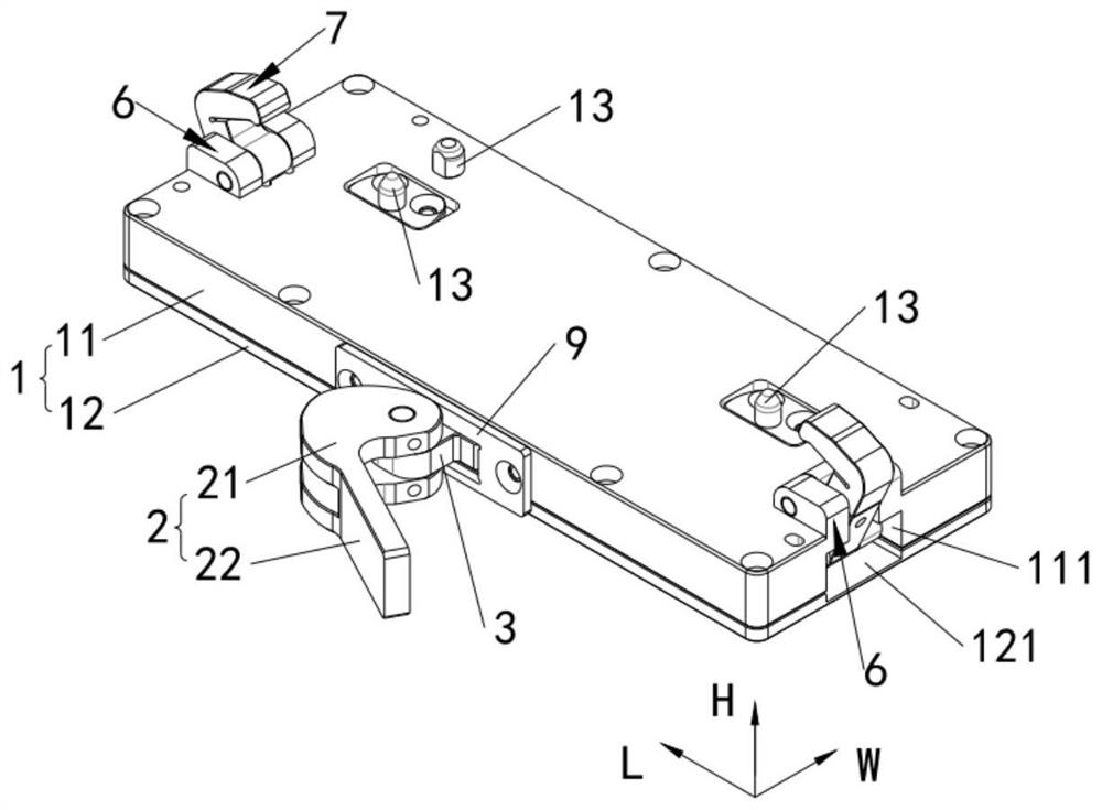
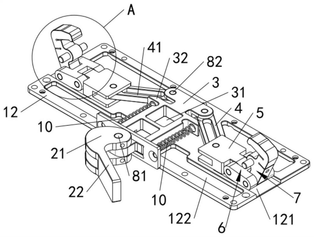
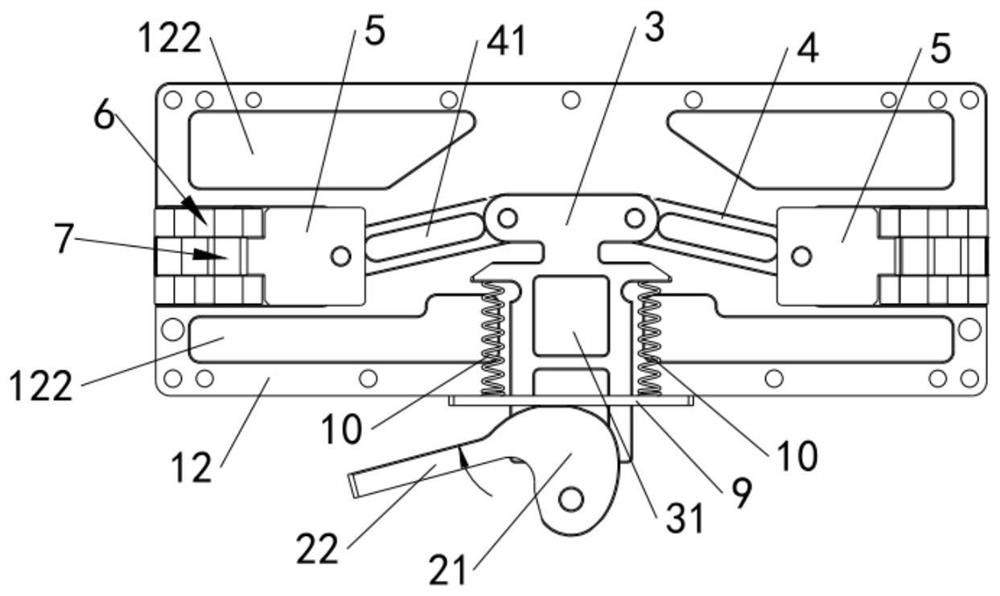
[0045] Such as figure 1 with figure 2 As shown, this embodiment provides a manual positioning and clamping device, including a workbench 1, a cam handle 2, a first connecting rod 3, two second connecting rods 4, two sliding blocks 5, and two floating blocks 6 And two claws 7, wherein, the upper surface of workbench 1 is used for p...


PUM


Abstract

The invention relates to the field of clamping equipment, and particularly discloses a manual positioning and clamping device. The manual positioning and clamping device comprises a workbench, a cam handle, a first connecting rod, second connecting rods, sliding blocks, floating blocks and clamping jaws. The first connecting rod moves in the first horizontal direction by rotating the cam handle, the second connecting rods are driven to rotate relative to the first connecting rod and the corresponding sliding blocks, and then the second connecting rods are used for pushing the corresponding sliding blocks to move in the second horizontal direction. Then, the sliding blocks drive the corresponding floating blocks to rotate, the corresponding clamping jaws rotate around hinged shafts of the clamping jaws, and therefore the second ends of the two clamping jaws get close to each other or get away from each other so as to clamp or loosen a workpiece located on a cover plate. The manual positioning and clamping device is simple in structure, after the workpiece is placed on the workbench, the workpiece can be clamped and loosened through the clamping jaws only by rotating the cam handle to drive the first connecting rod, the second connecting rods, the sliding blocks and the floating blocks to act, the clamping mode is simple, operation is fast, and the clamping efficiency is improved.

Description

technical field [0001] The invention relates to the field of clamping equipment, in particular to a manual positioning and clamping device. Background technique [0002] Before the parts are processed, the parts need to be fixed. At present, the characteristics of incoming parts are usually used, and the parts to be processed are manually clamped to the bench vise or fixture. The clamping process is cumbersome, resulting in low clamping efficiency. [0003] Therefore, there is an urgent need for a manual positioning and clamping device to solve the above technical problems. Contents of the invention [0004] The purpose of the present invention is to provide a manual positioning and clamping device, which can simplify the clamping process and improve the clamping efficiency. [0005] For reaching this purpose, the present invention adopts following technical scheme: [0006] A manual positioning and clamping device, comprising: [0007] a workbench, the upper surface o...

Claims


Application Information

Patent Timeline
Patent Type & Authority Applications(China)
IPC IPC(8): B25B11/00
CPCB25B11/00
Inventor 徐文飞刘红燕
Owner 苏州润弘安创自动化科技有限公司
Why Eureka
Try Eureka