Injection molding machine, control unit, and cooling unit

A technology for injection molding machines and cooling units, which is applied in the field of control panels, cooling units, and injection molding machines, and can solve problems such as unstable movements of the control system

Active Publication Date: 2020-10-09
SUMITOMO HEAVY IND LTD
View PDF11 Cites 0 Cited by
  • Summary
  • Abstract
  • Description
  • Claims
  • Application Information

AI Technical Summary

Problems solved by technology

Dust may cause unintended short circuit between electrical components or unintended heat accumulation of electrical components, which may destabilize the operation of the control system stored in the housing

Method used


Image

  • Injection molding machine, control unit, and cooling unit
  • Injection molding machine, control unit, and cooling unit
  • Injection molding machine, control unit, and cooling unit

Examples


Embodiment Construction

[0032] Below, refer to Figure 1 to Figure 5 Non-limiting embodiments and features of the present invention will be described. Those skilled in the art can combine the various embodiments and / or individual features without too much explanation, and can also understand the synergistic effect based on the combination. In principle, overlapping descriptions between the embodiments are omitted. The accompanying drawings are for the main purpose of describing the invention and have been simplified for ease of drawing. Each feature is not only valid for the injection molding machine disclosed in this specification, but can also be understood as a general feature that can be commonly used in various other injection molding machines not disclosed in this specification.

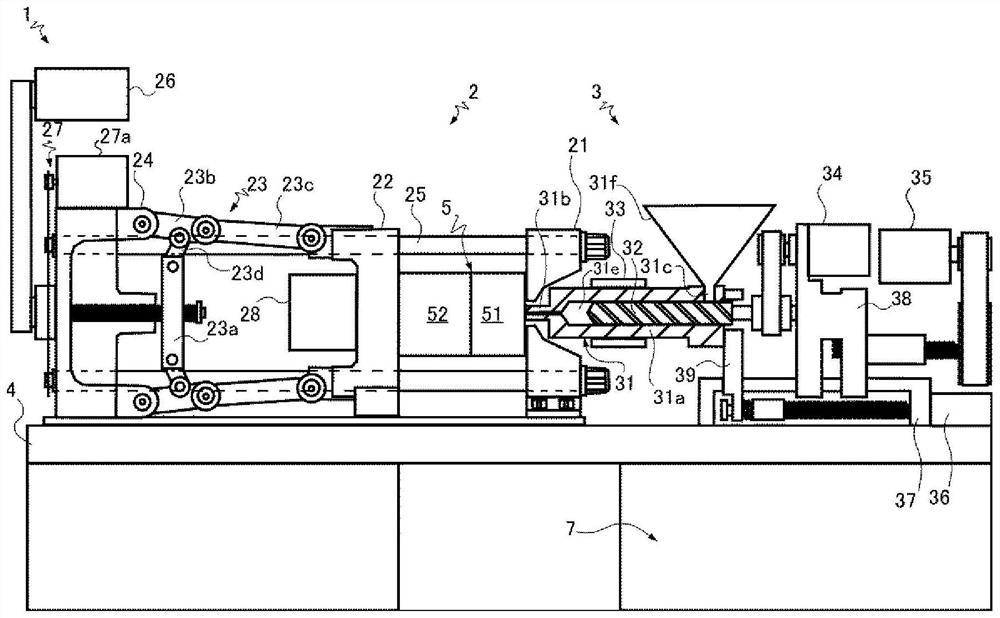
[0033] Such as figure 1 As shown, the injection molding machine 1 has a mold clamping device 2 and an injection device 3 mounted on a common or different base 4 . The injection molding machine 1 continuously manuf...


PUM


Abstract

The invention relates to an injection molding machine, a control unit, and a cooling unit. A control unit (7) of an injection molding machine (1) includes a motor driving element (9) disposed in an internal space of the control unit housing (71), and a cooling unit (8) for cooling the motor driving element (9). The cooling unit (8) includes a flow path member (8) including a heat sink (81c) thermally connected to the motor driving element (9), and at least one first fan (F) forming a flow path (82) together with at least the flow path member (8), and configured to generate a first airflow flowing through the flow path (82) . The flow path (82) has an inlet (82a) in a first side surface portion (71b) of the control unit housing (71), has an outlet (82b) in a second side surface portion (71e) of the control unit housing (71), and is configured so that an operation of the first fan (F) prevents the first airflow flowing in the flow path (82) from flowing out to the internal space of the control unit housing (71).

Description

technical field [0001] This application claims priority based on Japanese Patent Application No. 2019-069417 filed on March 29, 2019. The entire contents of this Japanese application are incorporated herein by reference. [0002] The invention relates to an injection molding machine, a control panel and a cooling unit. Background technique [0003] Patent Document 1 discloses that a radiator and a cooling fan are provided in a casing. The airflow generated by the operation of the cooling fan flows through the flow path between the fins of the radiator, and flows out of the casing through the casing window. [0004] Patent Document 1: Japanese Patent No. 4100660 [0005] As disclosed in Patent Document 1, when a radiator and a fan are provided in the housing, an air flow is generated in the housing as the fan operates. As a result, cooling of heat-generating elements (for example, CPU) other than the IPM (Intelligent Power Module: Intelligent Power Module) inside the hous...

Claims


Application Information

Patent Timeline
Patent Type & Authority Applications(China)
IPC IPC(8): B29C45/72B29C45/17
CPCB29C45/72B29C45/1753B29C2045/7271B29C45/1774
Inventor 丸田阳介豊岛研人江幡宏一郎根本拓也山口宏小沼淳一
Owner SUMITOMO HEAVY IND LTD
Why Eureka
Try Eureka