Tooling device and method for measuring casting thickness
What is AI technical title?
AI technical title is built by Patsnap AI team. It summarizes the technical point description of the patent document.
A tooling and thickness measurement technology, applied in measuring devices, instruments, using wave/particle radiation, etc., can solve the problems of inaccurate measurement of hollow blades, and achieve the effects of simple and convenient card installation, short detection period, and wide application range.
Active Publication Date: 2022-04-01
AECC AVIATION POWER CO LTD
View PDF10 Cites 0 Cited by
Summary
Abstract
Description
Claims
Application Information
AI Technical Summary
This helps you quickly interpret patents by identifying the three key elements:
Problems solved by technology
Method used
Benefits of technology
Problems solved by technology
[0004] In order to solve the problems existing in the prior art, the present invention provides a tooling device for measuring the thickness of castings, which solves the problem of inaccurate measurement of the R position of the hollow blade in the prior art
Method used
Image
Click on the blue label to locate the original text in one second.
Reading with bidirectional positioning of images and text.
Examples
Embodiment 1
[0047] Example 1: Detection of the wall thickness of the inlet R of a high-pressure turbine blade of a certain machine
[0048] The blade body size of the hollow blade to be tested is less than 50mm, so only the tooling device for measuring the thickness of the casting is used. The selected size of the tooling device is:
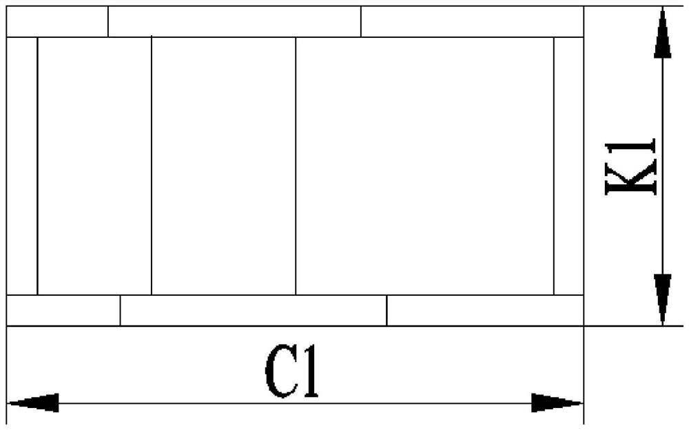
[0053] The wall thickness of tenon root placement board, edge board placement board, tenon root support board and reinforced tooling board is 3mm, C1=50mm, K1=31mm.
[0054] Make a thickness measuring tooling device according to the above dimensions, place the hollow blade on the tooling device, put the placed hollow blade and the tooling device into the CR testing eq...
Embodiment 2
[0055] Example 2: Detection of the wall thickness of the inlet R of the working blade of a high-pressure turbine of a certain machine
[0056] The blade body size of the hollow blade to be tested is about 126mm, and the casting thickness measuring tooling device and auxiliary tooling parts are used for detection. The dimensions of the tooling device and auxiliary tooling parts are as follows:
[0061] The wall thickness of tenon root placement board, edge board placement board, tenon root support board and reinforced tooling board is 3mm, C1=86mm, K1=56mm;
[0063] Make the tooling device and auxiliary tooling parts according ...
PUM
Abstract
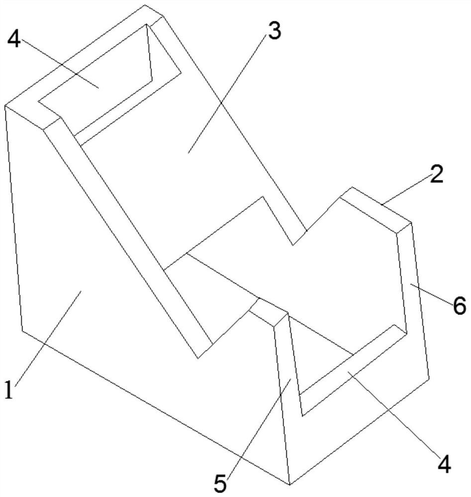
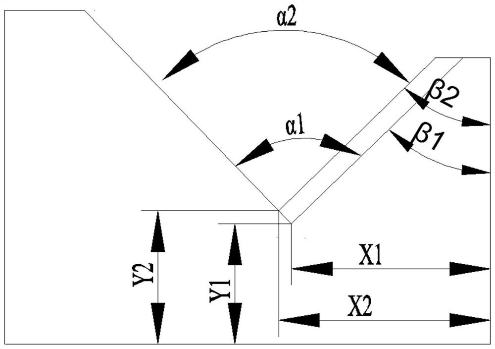
The invention discloses a tooling device for measuring the thickness of a casting and a method thereof. The degree is equal to the included angle between the end face of the tenon root inlet side and the end face of the tenon root on the back side of the blade; The included angle between the reference side, the first reference side and the V-shaped opening of the tenon root is β1, and the opening degree of the V-shaped opening of the tenon root is α1, and the β1 is equal to the angle between the end face of the tenon root inlet side and the vertical CR ray Angle, the structure of the edge plate placement plate is the same as that of the tenon root placement plate, wherein the angle between the second reference edge and the V-shaped opening of the edge plate is β2, and the opening degree of the V-shaped opening of the edge plate is α2, and the β2 is equal to The angle between the end surface 13 of the inlet side of the edge plate and the vertical CR ray, after the hollow blade is placed in the present invention, the plane where the R part of the hollow blade inlet side is located is perpendicular to the detection ray, and the detection ray can detect the vertical distance of the R component , making the measured wall thickness of the R part more accurate.
Description
technical field [0001] The invention belongs to the field of measuring devices for hollow blades, in particular to a tooling device for measuring the thickness of castings and a method thereof. Background technique [0002] Wall thickness is one of the key characteristics of hollow blades of aero-engines and gas turbines. If the wall thickness is too thin, it will affect the strength, and if the wall thickness is too thick, it will cause overweight. Accurate measurement of wall thickness has become a key point in the quality control of hollow blades. [0003] At present, the wall thickness of hollow blades is detected by ultrasonic thickness measurement or CT. The radius of curvature of the inlet R of the hollow blade is large, and the ultrasonic thickness measurement method is adopted. Since the probe of the ultrasonic thickness gauge is a plane, the contact with the inlet R of the inlet side is a point contact, and the wall thickness of the inlet R cannot be measured with ...
Claims
Application Information
Patent Timeline
Application Date:The date an application was filed.
Publication Date:The date a patent or application was officially published.
First Publication Date:The earliest publication date of a patent with the same application number.
Issue Date:Publication date of the patent grant document.
PCT Entry Date:The Entry date of PCT National Phase.
Estimated Expiry Date:The statutory expiry date of a patent right according to the Patent Law, and it is the longest term of protection that the patent right can achieve without the termination of the patent right due to other reasons(Term extension factor has been taken into account ).
Invalid Date:Actual expiry date is based on effective date or publication date of legal transaction data of invalid patent.

