Wireless vibration sensor

A wireless vibration and sensor technology, applied in the direction of instruments, scientific instruments, measuring instrument components, etc., can solve the problems of uneven sealing effect of sensors, reduced service life of sensors, lack of wireless vibration sensors, etc., to achieve simple structure and easy disassembly , the effect of improving accuracy

Inactive Publication Date: 2020-10-09
常州润田电子科技有限公司
View PDF6 Cites 2 Cited by
  • Summary
  • Abstract
  • Description
  • Claims
  • Application Information

AI Technical Summary

Problems solved by technology

[0003] In some dusty or humid environments, the requirements for the use of sensors are relatively high. During long-term use, more impurities and dust will accumulate on the surface of the sensor. If dust enters the sensor, it will cause problems such as short circuit of the sensor and reduce the sensor. However, the sealing effect of the sensor itself is uneven. Therefore, a protective shell is usually inserted outside the sensor body to improve the dustproof effect. However, the existing protective shell is inconvenient to disassemble. Therefore, there is a lack of a convenient Wireless shock sensor with case removed

Method used


Image

  • Wireless vibration sensor
  • Wireless vibration sensor
  • Wireless vibration sensor

Examples


Embodiment 1

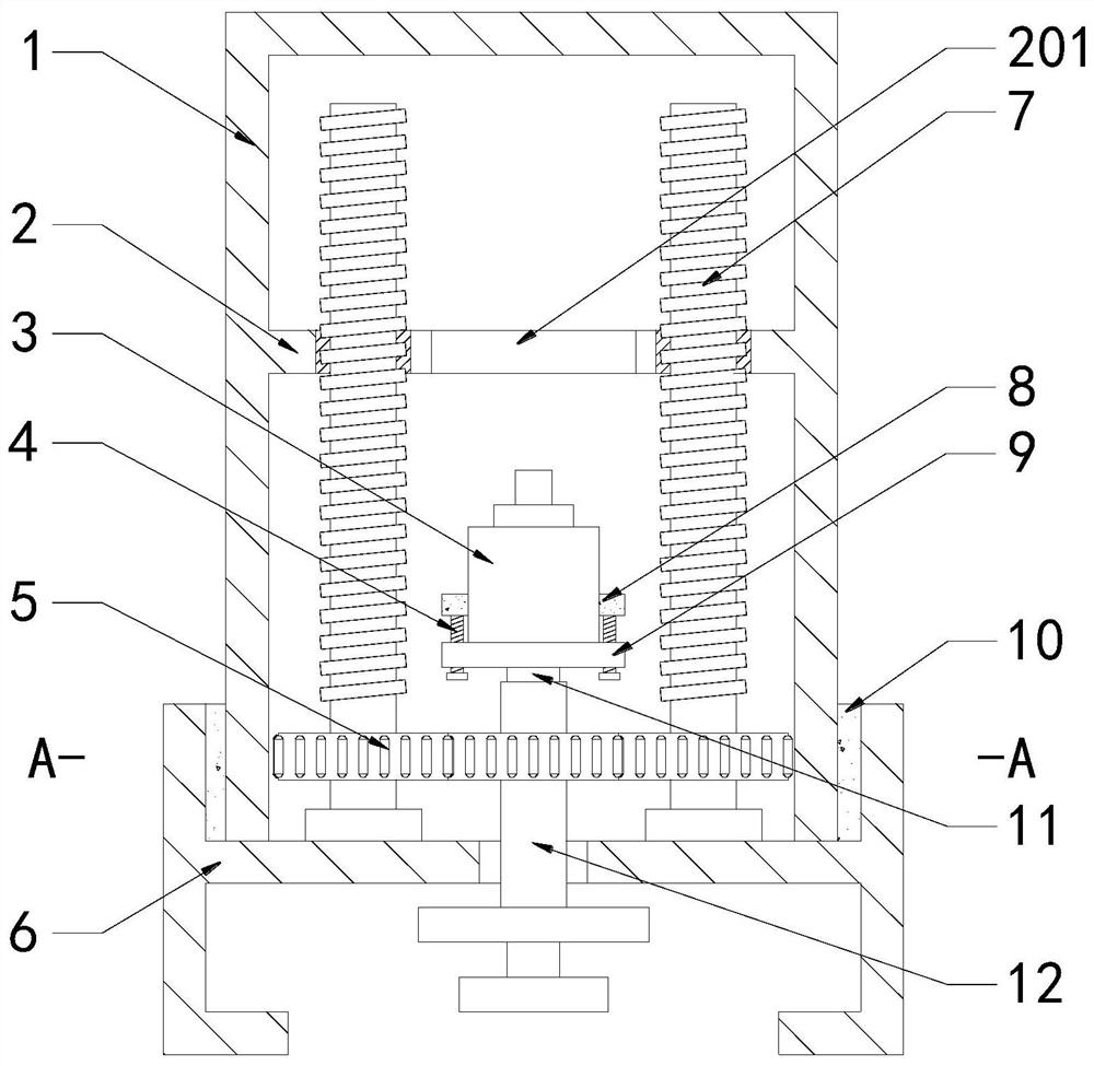
[0029] see Figure 1-4 , a wireless vibration sensor, including a sensor body 3, a protective shell 1 is arranged on the outside of the sensor body 3, and a fixed base 6 is arranged on the bottom, the protective shell 1 is socketed in the groove on the top of the fixed base 6, and the protective shell 1 is socketed on the sensor body 3, to prevent dust from entering the sensor body 3 and causing damage, the bottom of the fixed base 6 is rotatably connected with a rotating sleeve 12, and both sides of the inner surface wall at the bottom of the fixed base 6 are installed with threaded rods 7 through bearing rotation, and the two sides of the protective shell 1 near the top A fixed plate 2 is fixedly connected between the side inner surface walls, and the extension end of the top of the threaded rod 7 runs through the fixed plate 2, and the penetration is screwed and connected. On the one hand, the rotation of the fixed plate 2 is restricted to ensure that the protective shell 1 ...

Embodiment 2

[0033] The difference from Example 1 is that

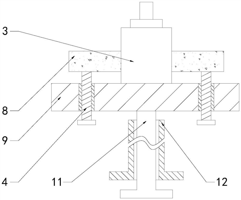
[0034] see figure 1 and image 3 , the inside of the rotating sleeve 12 is sleeved with a rotating rod 11, the top of the rotating rod 11 is fixedly connected with a rotating plate 9, the sensor body 3 is placed on the rotating plate 9, and the rotating rod 11 is rotated to drive the rotating plate 9 to rotate, thereby changing the sensor body 3, it is convenient for the sensor body 3 to receive signals from different directions, so as to improve the accuracy of detection.

Embodiment 3

[0036] The difference from Example 1 is that

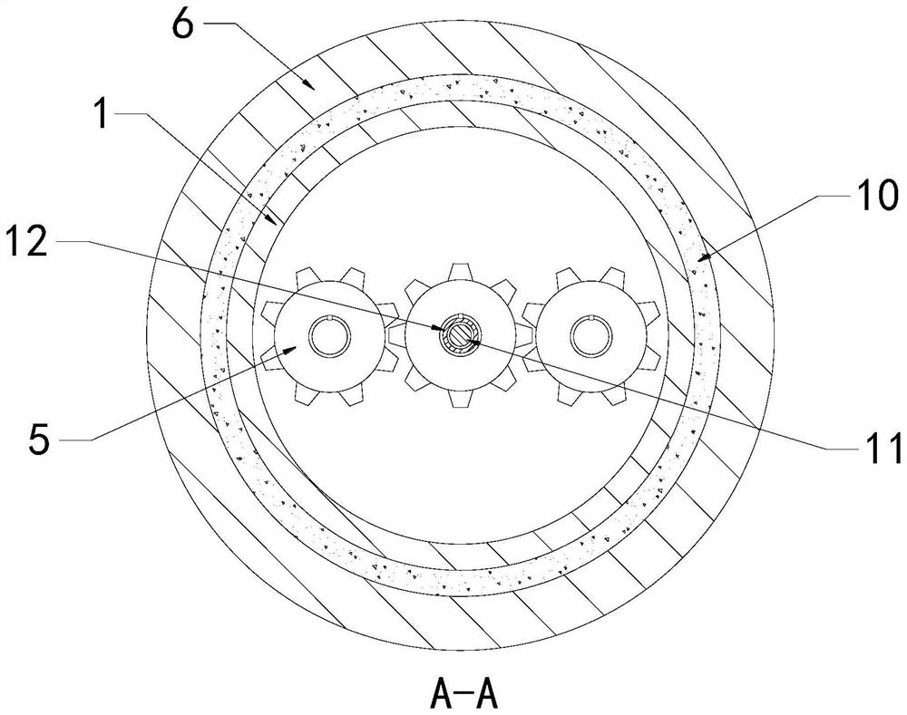
[0037] see figure 1 , image 3 and Figure 4 The outside of the sensor body 3 is distributed with a plurality of eccentric wheels 13 around its circumference, and the bottom of the rotating plate 9 runs through an adjusting screw 4, which is threaded and connected, and the extension end of the top of the adjusting screw 4 is fixedly connected with the eccentric wheel 13, and Their axis lines are offset from each other, by turning a plurality of adjusting screw rods 4 respectively, the eccentric wheel 13 is driven to rotate until the eccentric wheel 13 clamps the sensor body 3 between them, and when the adjusting screw rod 4 is rotated in the opposite direction, the eccentric wheel is loosened 13 The clamping of the sensor body 3 facilitates the disassembly and assembly of the sensor body 3. Since the eccentric wheels 13 have different radii of rotation, it is convenient to clamp and install sensor bodies 3 of different sizes. Th...


PUM


Abstract

The invention discloses a wireless vibration sensor. The sensor comprises a sensor body, a protective shell is arranged on the outer side of the sensor body, a fixing base is arranged at the bottom ofthe sensor body, the protective shell is sleeved with a groove in the top of the fixing base, a rotating sleeve is rotatably connected to the bottom of the fixing base, and threaded rods are rotatably installed on the two sides of the inner surface wall of the bottom of the fixing base through bearings. In the present invention, the rotating sleeve rotates forwards, a gear serving as a driving wheel is driven to rotate, according to the meshing transmission principle of latches, gears serving as driven wheels on the two sides are driven to rotate reversely, the threaded rods are driven to rotate, according to the thread transmission principle, a fixing plate is driven to move upwards, then the protective shell is driven to be away from the fixing base until the fixing plate is separated from the threaded rods, dismounting of the protective shell and reverse operation of the rotating sleeve are completed, finally, mounting of the protective shell can be achieved, the structure is simple, dismounting and mounting are convenient, and the protective shell can be repeatedly recycled and is high in economic practicability.

Description

technical field [0001] The invention relates to the technical field of wireless vibration sensors, in particular to wireless vibration sensors. Background technique [0002] The wireless vibration sensor is a machine condition monitoring based on wireless technology. It has the functions of vibration measurement and temperature measurement. It is easy to operate and automatically indicates the status alarm. It is used in industrial equipment status management and monitoring control systems; it is suitable for on-site equipment operation and maintenance personnel to monitor equipment status. Find problems in time to ensure normal and reliable operation of equipment. [0003] In some dusty or humid environments, the requirements for the use of sensors are relatively high. During long-term use, more impurities and dust will accumulate on the surface of the sensor. If the dust enters the sensor, it will cause problems such as short circuit of the sensor and reduce the sensor. s...

Claims


Application Information

Patent Timeline
Patent Type & Authority Applications(China)
IPC IPC(8): G01D21/02G01D11/30G01D11/24G01H17/00G01K13/00
CPCG01D11/24G01D11/30G01D21/02G01H17/00G01K13/00
Inventor 祝卫平蒋伟
Owner 常州润田电子科技有限公司
Why Eureka
Try Eureka