Optical fiber current sensor for realizing non-reciprocal dynamic phase modulation and corresponding signal demodulation method

A phase modulator and dynamic phase technology, applied in nonlinear optics, voltage/current isolation, measuring current/voltage, etc., can solve problems such as inability to meet current measurement requirements in new scenarios, and achieve improved measurement range, reduced noise, and high Measuring Bandwidth Effects

Active Publication Date: 2020-10-09
浙江康阔光智能科技有限公司
View PDF9 Cites 2 Cited by
  • Summary
  • Abstract
  • Description
  • Claims
  • Application Information

AI Technical Summary

Problems solved by technology

Due to the limitations of the above two main types of fiber optic current sensors, they cannot meet the current measurement requirements of these new scenarios, and the fiber optic current sensors further expand their performance indicators to meet the needs of the above measurement scenarios

Method used


Image

  • Optical fiber current sensor for realizing non-reciprocal dynamic phase modulation and corresponding signal demodulation method
  • Optical fiber current sensor for realizing non-reciprocal dynamic phase modulation and corresponding signal demodulation method
  • Optical fiber current sensor for realizing non-reciprocal dynamic phase modulation and corresponding signal demodulation method

Examples


Embodiment Construction

[0035] In order to describe the technical content of the present invention more clearly, further description will be given below in conjunction with specific embodiments.

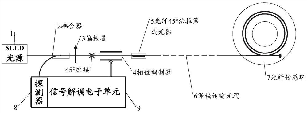
[0036] The fiber-optic current sensor realizing non-reciprocal dynamic phase modulation of the present invention includes a low-polarization SLED light source 1, a fiber coupler 2, a fiber polarizer 3, a straight waveguide phase modulator 4, a Faraday rotator 5, and a polarization-maintaining transmission Optical cable 6, optical fiber sensing ring 7, detector 8 and signal demodulation electronic unit 9, described low-bias type SLED light source 1 is connected to optical fiber coupler 2 through single-mode optical fiber; described optical fiber coupler 2 and optical fiber polarization The optical fiber polarizer 3 is fused with the straight waveguide phase modulator 4 at 45°, and the other end of the straight waveguide phase modulator 4 is fused with the input end of the Faraday rotator 5; the Faraday The o...


PUM


Abstract

The invention relates to an optical fiber current sensor for realizing non-reciprocal dynamic phase modulation. The optical fiber current sensor comprises a low-polarization SLED light source, an optical fiber coupler, an optical fiber polarizer, a straight waveguide phase modulator, a Faraday rotator, a polarization-maintaining transmission optical cable, an optical fiber sensing ring, a detectorand a signal demodulation electronic unit, wherein the low-polarization SLED light source is connected to the optical fiber coupler through a single-mode optical fiber; and the optical fiber coupleris welded with the optical fiber polarizer. The invention also relates to a signal demodulation method for realizing non-reciprocal dynamic phase modulation. The optical fiber current sensor for realizing non-reciprocal dynamic phase modulation and the corresponding signal demodulation method are adopted, modulation of fixed phase bias can be achieved, modulation of dynamic feedback can also be achieved, noise caused by frequent modulation of the current sensor can be lowered, small signal measurement precision can be improved, meanwhile, high measurement bandwidth can be obtained, dynamic modulation can be conducted according to the magnitude of current detected in real time, and the measurement range of the current sensor is widened.

Description

technical field [0001] The invention relates to the field of optoelectronic technology, in particular to the field of optical fiber sensing, in particular to an optical fiber current sensor for realizing non-reciprocal dynamic phase modulation and a corresponding signal demodulation method. Background technique [0002] Currently, fiber optic current sensors widely used in power measurement, industrial electrolysis and other fields are mainly realized by Sagnac interferometric digital closed-loop modulation scheme. ability. In order to make the fiber optic current sensor work in the optimal region of linear characteristics, it is necessary to apply a modulation signal through a phase modulator so that the sensor operating point is located at ±π / 2 phase. The part of the optical path including the phase modulator is a part of the reciprocal optical path, and the phase modulation cannot make the operating point work at +π / 2 or -π / 2 all the time, because the result of the phase...

Claims


Application Information

Patent Timeline
Patent Type & Authority Applications(China)
IPC IPC(8): G01R19/25G01R15/24G02F1/01
CPCG01R19/2506G01R15/246G02F1/0115
Inventor 彭耐黄勇许宗幸
Owner 浙江康阔光智能科技有限公司
Why Eureka
Try Eureka