Material taking mechanism of rapid assembly equipment for capacitor machining

A technology of mechanical processing and assembling equipment, which is applied in the direction of capacitors, capacitor manufacturing, circuits, etc., can solve the problems of capacitor damage, high maintenance cost, high cost, etc., and achieve the effect of close connection, simple stroke, streamlined and efficient driving components

Active Publication Date: 2020-10-09
嘉兴考普诺机械科技有限公司
View PDF9 Cites 0 Cited by
  • Summary
  • Abstract
  • Description
  • Claims
  • Application Information

AI Technical Summary

Problems solved by technology

[0004] Due to the slurry inside the capacitor, it is very easy to be pinched when clamping, while the conventional claw structure is easy to leave pinch marks on the surface of the capacitor, and in severe cases, it is easy to cause damage to the capacitor. In addition, clamping and transfer are usually Two independent transmission parts need two sets of control systems in series to complete. Not only the cost is high, but also the operation logic needs to be designed. Once damaged, the maintenance cost is high

Method used


Image

  • Material taking mechanism of rapid assembly equipment for capacitor machining
  • Material taking mechanism of rapid assembly equipment for capacitor machining
  • Material taking mechanism of rapid assembly equipment for capacitor machining

Examples


Embodiment

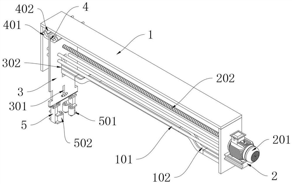
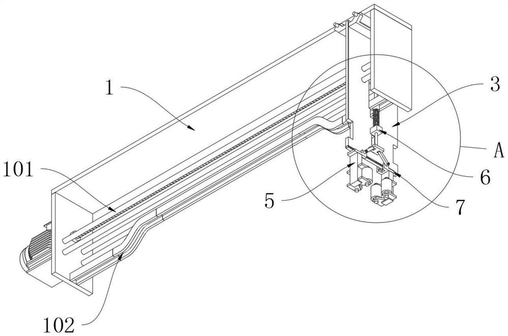
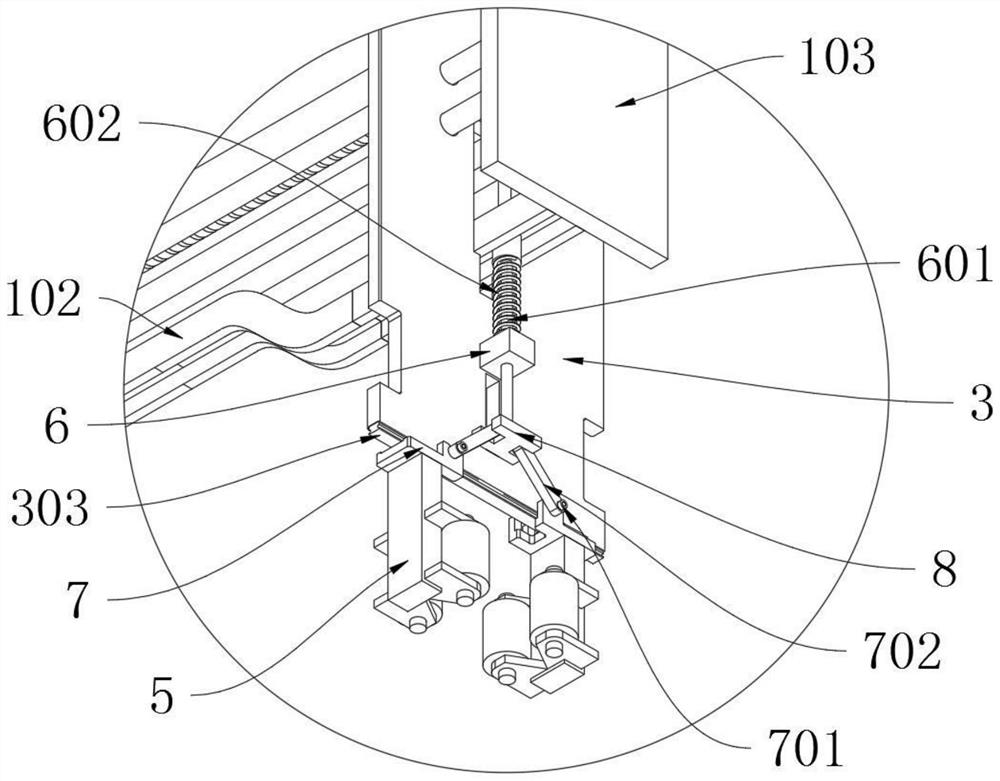
[0037] as attached figure 1 to attach Figure 8 Shown:

[0038] The present invention provides a material retrieving mechanism for rapid assembly equipment for machining capacitors, which includes a truss 1; a horizontal drive mechanism 2 is installed laterally at the lower end of the truss 1; the truss 1 includes a guide rod 101, a guide rail 102 and an end plate 103, The end plate 103 is fixedly installed vertically downward at the left end edge and the right end edge of the bottom plane of the truss 1, and four guide rods 101 arranged in a rectangular shape are fixedly installed between the two end plates 103, while the reclaimer 3 is Slidingly sleeved on the guide rod 101, the lower ends of the opposite side walls of the two end plates 103 are fixedly equipped with guide rails 102 with low middle parts and high left and right ends, and the front and rear edges of the guide rails 102 are all fixed. A protruding edge plate is installed, and the guide rail 102 slides throug...


PUM


Abstract

The invention provides a material taking mechanism of rapid assembly equipment for capacitor machining, and relates to the technical field of capacitor processing. In the prior art, due to slurry wrapping inside a capacitor, the capacitor is easily damaged in a clamping process, a conventional clamping jaw type structure easily causes clamping marks on the surface of the capacitor, and the capacitor is prone to being damaged when the clamping marks are severe; and clamping and transferring are usually achieved through two independent transmission parts and need to be completed through two setsof control systems connected in series, so that the cost is high, operation logic needs to be designed, and once the capacitor is damaged, the maintenance cost is high. The material taking mechanismcomprises a truss, wherein a horizontal driving mechanism is transversely mounted at the lower end of the truss. According to the invention, due to the fact that a servo motor is fixedly installed atthe upper end of a drive mechanism, when a material taking frame moves to the two ends of a guide rail, discharging is conducted, the middle of the guide rail is in a clamping state, and columnar capacitors in a material box can be clamped to a conveying belt to be packaged and machined, so that convenience and rapidness are achieved, the stroke is simple, and drive components are simple and efficient.

Description

technical field [0001] The invention relates to the technical field of capacitor processing, and more specifically relates to a material retrieving mechanism of a rapid assembly equipment for capacitor machining. Background technique [0002] During the capacitor production process, a gripping device is required to hold and transport the capacitor. [0003] For example, a device for clamping capacitors in the patent application CN201310315111.7, which includes a frame and a first clamping mechanism arranged on the frame, the first clamping mechanism includes a first clamping head and a second clamping The first clamping part of the head, the first pen-shaped cylinder and the first connecting frame arranged on the frame are connected to the first connecting frame so as to be movable along its own axis and fixed to the output rod of the first pen-shaped cylinder The connected first push rod, one end of which is hinged to the first push rod and the first connecting rod whose m...

Claims


Application Information

Patent Timeline
Patent Type & Authority Applications(China)
IPC IPC(8): H01G13/00
CPCH01G13/00
Inventor 金诗佳
Owner 嘉兴考普诺机械科技有限公司
Why Eureka
Try Eureka