
Laser stitch welding method for circular welding seam of thin steel plate

A thin steel, circular technology, applied in the field of laser lap welding of thin steel circular welds, can solve problems such as uneven heat input, impact on molten pool, incomplete penetration, etc., to ensure uniformity and avoid local stress concentration , Good effect of integration

Active Publication Date: 2022-06-24
CHANGZHOU INST OF ADVANCED MFG TECH
View PDF12 Cites 0 Cited by
  • Summary
  • Abstract
  • Description
  • Claims
  • Application Information

AI Technical Summary

Problems solved by technology

[0005] The purpose of the present invention is to overcome the deficiencies of the prior art and provide a laser lap welding method for circular weld seams of thin steel plates, which can solve the problem of uneven heat input during the welding process while avoiding the impact of the laser thermal relaxation effect on the molten pool problems, thereby eliminating the common defects such as local incomplete penetration, pits, burn-through, etc. of such circular welds

Method used


Image

  • Laser stitch welding method for circular welding seam of thin steel plate
  • Laser stitch welding method for circular welding seam of thin steel plate

Examples


Embodiment Construction

[0028] The embodiments of the present invention are described in detail below. This embodiment is implemented on the premise of the technical solution of the present invention, and provides a detailed implementation manner and a specific operation process, but the protection scope of the present invention is not limited to the following implementation. example.

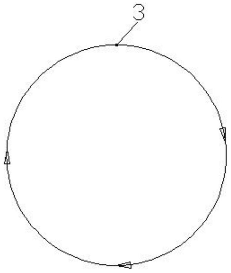
[0029] see Figure 1 to Figure 2 , This embodiment discloses a laser stitch welding method for circular welds of thin steel plates. The laser stitch welding method is used for welding circular welds 2 on two thin steel plates 1 , and the thin steel plates 1 are preferably stainless steel thin plates.

[0030] The laser stitch welding method is performed in sequence as follows:

[0031] Step 1. Preset the welding travel speed v of the laser processing head, and calculate the welding travel duration t of the laser processing head according to the formula t=C / v, where C is the circumference of the circular weld 2, accor...


PUM

PropertyMeasurementUnit
thicknessaaaaaaaaaa

Abstract

The invention discloses a laser stitch welding method for a circular weld joint of a thin steel plate, which comprises the following steps: firstly, presetting the welding advancing speed v of a laser processing head, and calculating the value of each time length according to the welding advancing speed v; the laser processing head stays above the starting point of the circular weld joint for t1, and the laser power is gradually increased from zero; the laser processing head starts to advance at a constant speed along the track of the circular weld joint at v, and when the advancing time is t3-t1, the laser power is increased to constant power; the laser processing head continues to advance at a constant speed for a time length t5, and the laser power is kept constant; the laser processing head continues to advance at a constant speed, and the laser power is gradually reduced from constant power; and the laser processing head stays above the termination point of the circular weld joint for t2, the laser power is continuously reduced to zero, and the welding is finished. The method has the advantages that heat input in the welding process is controlled by adopting a mode of combining control of the stroke of the laser processing head and control of laser power change, the problem that defects such as incomplete penetration, burn-through and pits are locally generated is solved, the shape of a welding seam is adjusted, and the welding quality is improved.

Description

technical field [0001] The invention relates to the technical field of laser welding, in particular to a laser stitch welding method for circular welding seams of thin steel plates. Background technique [0002] The superimposed welding seam of circular trajectory is common in the plate heat exchanger industry. The circular welding seam is the main pressure bearing position of the heat exchanger, and its welding quality directly affects the overall mechanical properties, sealing and service life of the heat exchanger plate. [0003] In traditional laser welded plate heat exchangers, it is common to see defective products caused by local virtual welding in circular welds. Analyzing its causes, it will be found that the size of such circular welds is small and the ends of the circular welds are overlapped. The superposition of the two sheet metal workpieces causes a gap between the two sheets. In addition, the acceleration and deceleration process when the motion mechanism sta...

Claims


Application Information

Patent Timeline
Patent Type & Authority Applications(China)
IPC IPC(8): B23K26/21B23K26/70
CPCB23K26/21B23K26/702Y02P70/10
Inventor 蒋一莉孙鹏曹凯花加丽张雅堃王芸
Owner CHANGZHOU INST OF ADVANCED MFG TECH
Learn More