Switch cabinet for preventing arcing ejection

A switchgear and arcing technology, applied in substation/switch layout details, anti-war damage, special equipment for doors/windows, etc. Twisted and complex, structurally strong effects

Active Publication Date: 2020-10-09
TIANJIN PINGGAO INTELLIGENT ELECTRIC +2
View PDF8 Cites 0 Cited by
  • Summary
  • Abstract
  • Description
  • Claims
  • Application Information

AI Technical Summary

Problems solved by technology

[0005] The purpose of the present invention is to provide a switchgear for preventing the blowout of the arc, so as to solve the technical problem in the prior art that the

Method used


Image

  • Switch cabinet for preventing arcing ejection
  • Switch cabinet for preventing arcing ejection
  • Switch cabinet for preventing arcing ejection

Examples


Embodiment 1

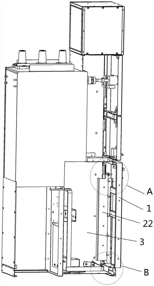
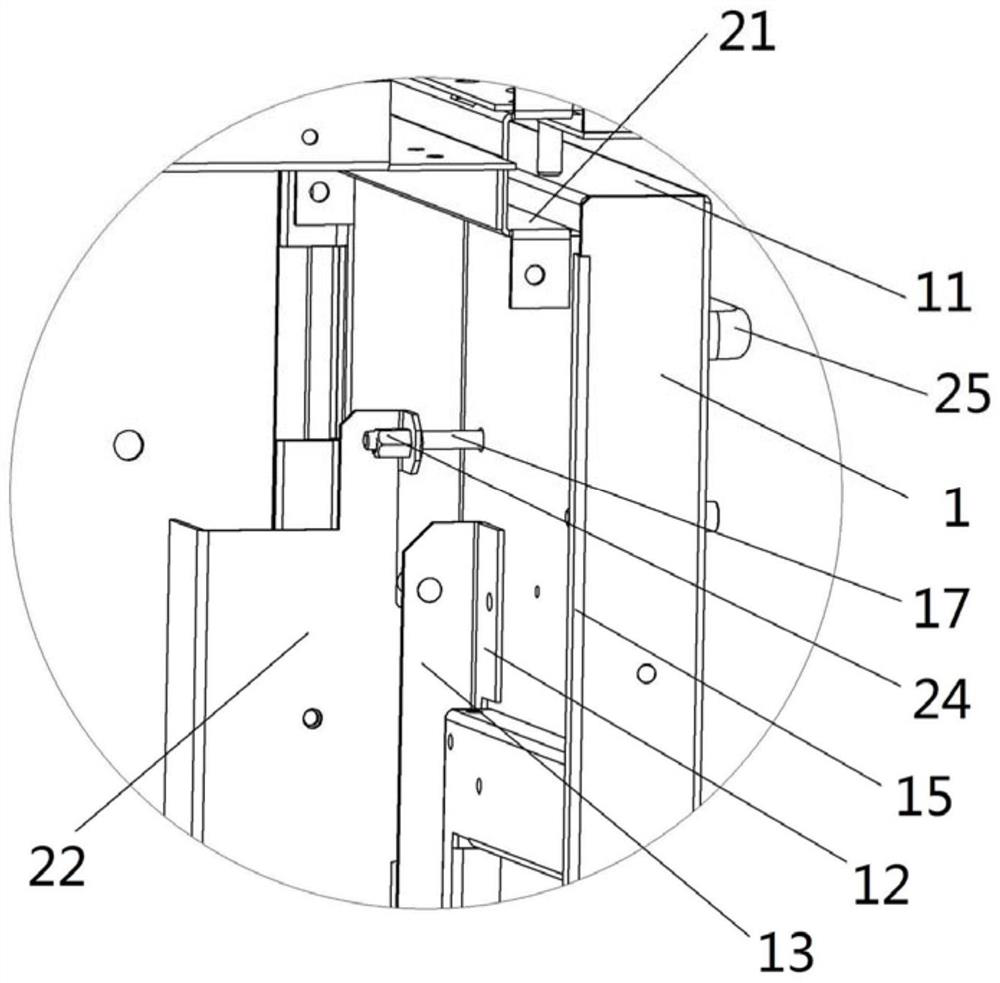
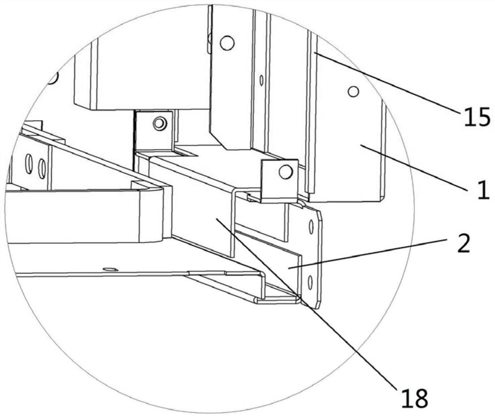
[0046] Such as figure 1 , figure 2 , image 3 and Figure 4 As shown, the switchgear used to prevent arc blowout of the present invention includes a cabinet door 1 and a cabinet body 3, the cabinet body 3 is provided with a cabinet door frame 2, and the cabinet door 1 is hung on the cabinet body door frame from top to bottom 2 on. The upper end of the cabinet door 1 is provided with a hanger 11 on the cabinet door, and a hanger 21 on the door frame is provided at a position corresponding to the hanger 11 on the door frame 2 of the cabinet body, wherein the hanger 11 on the door is bent downwards, and The pendant 21 is bent upwards, and when the cabinet door 1 is hung on the cabinet door frame 2, the hanger 11 on the cabinet door and the hanger 21 on the door frame form a hooking fit, so that there is a strong connection between the upper end of the cabinet door 1 and the cabinet door frame 2. The structural strength is high, and the high-pressure gas is not easy to push t...

Embodiment 2

[0059] The difference between the switchgear used to prevent arc blowout in this embodiment and the switchgear used to prevent arc blowout in embodiment 1 is that in embodiment 1, the hanger on the cabinet door and the hanger on the door frame All are right-angle bent plates. In this embodiment, in order to realize the hooking cooperation between the upper part of the cabinet door and the upper part of the door frame of the cabinet body, the hanger on the cabinet door is a downwardly bent cabinet door hook arranged on the upper end of the cabinet door. The cabinet door hook There are multiple and arranged at intervals. The door frame hanger is an upwardly bent door frame hook arranged on the upper end of the door frame. There are also multiple door frame hooks that correspond to the cabinet door hooks one by one.

Embodiment 3

[0061] The difference between the switchgear used to prevent arc blowout in this embodiment and the switchgear used to prevent arc blowout in embodiment 1 is that in embodiment 1, the vertical plate is formed by a right angle of the reinforcing plate side, and the reinforcing plate is installed on the cabinet door through bolts, and a plurality of retaining pins are arranged at intervals from top to bottom on the vertical plate. In order to realize the purpose of installing the retaining pins, in this embodiment, the vertical plate is directly welded on the The elongated steel plate on the door is formed, and the stop pin is arranged on the elongated steel plate.


PUM


Abstract

The invention relates to a switch cabinet for preventing arcing ejection, and belongs to the technical field of power switch equipment. The switch cabinet for preventing arcing ejection comprises a cabinet body provided with a cabinet body door frame and a cabinet door, the cabinet door is hung on the cabinet body door frame from top to bottom, a cabinet door upper hanging piece is arranged at theupper end of the cabinet door, and the cabinet door upper hanging piece is bent downwards; corresponding to the cabinet door upper hanging piece, a door frame upper hanging piece is arranged at the corresponding position of the cabinet body door frame, and the door frame upper hanging piece is bent upwards. When the cabinet door is hung on the door frame of the cabinet body, the cabinet door upper hanging piece and the door frame upper hanging piece are correspondingly hooked and matched, so that high structural strength is achieved between the upper end of the cabinet door and the door frame, high-pressure gas is not prone to ejecting the cabinet door open at the position, and then the high-pressure gas and arcing cannot be sprayed out from the position in quantity.

Description

technical field [0001] The invention belongs to the technical field of electric switchgear, and in particular relates to a switchgear for preventing arc blowout. Background technique [0002] When the ring distribution network supplies power to the outside through the distribution branch, a switchgear is required. This type of switchgear is generally called a ring network cabinet. For this type of switchgear, the internal arcing fault is a frequent and catastrophic serious fault, and once the fault occurs, it will radiate huge sound, light, electricity, heat and other energy, and in a short time The high-pressure gas generated by the internal fault arc will be released in the form of a gas explosion, which will have a strong impact on the cabinet, causing arcing and high-pressure gas to be ejected from the gap in the cabinet, and may even directly cause the cabinet to burst, making the operator People around the equipment may be seriously injured. [0003] The existing tec...

Claims


Application Information

Patent Timeline
IPC IPC(8): H02B1/30E06B3/70E06B5/10E06B7/28
CPCH02B1/30H02B1/306E06B3/70E06B5/10E06B7/28
Inventor 夏琨李传明张恒雪马昌飞李红雷刘宏玉王恩旭王茜陈轩丛艳伟张冬旭桑永建谢寅志
Owner TIANJIN PINGGAO INTELLIGENT ELECTRIC
Why Eureka
Try Eureka