Plate positioning device, material containing mechanism, machining center and machining method

A technology for positioning devices and plate processing, applied in positioning devices, metal processing, metal processing equipment, etc., to achieve the effects of reduced area occupation, convenient operation, and simplified structure

Pending Publication Date: 2020-10-13
全准数控设备(苏州)有限公司
View PDF3 Cites 2 Cited by
  • Summary
  • Abstract
  • Description
  • Claims
  • Application Information

AI Technical Summary

Problems solved by technology

[0012] 1. When the positioning device is not installed on the workbench,

Method used


Image

  • Plate positioning device, material containing mechanism, machining center and machining method
  • Plate positioning device, material containing mechanism, machining center and machining method
  • Plate positioning device, material containing mechanism, machining center and machining method

Examples


Embodiment 1

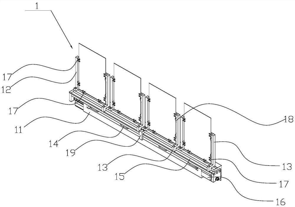
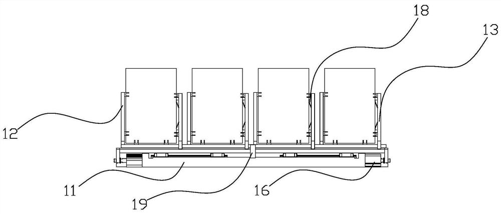
[0076] See attached Figure 1-2 , the embodiment of the present invention provides a plate positioning device 1, which is used for positioning the plate in the direction perpendicular to the machine tool of the plate processing center. The plate processing center includes a machine tool, a material tank and a workbench. Set parallel to the horizontal plane of the machine tool.

[0077] The positioning device 1 is an upright structure, which can be vertically arranged on the machine tool of the plate processing center and installed at the adjacent rear of the material trough, between the material trough and the workbench. In addition, the positioning device 1 can also be installed in front of the chute.

[0078] The positioning device 1 includes: a bracket 11 for installing the positioning device 1 on the plate processing center machine tool, a number of fixed positioning blocks 12 and movable positioning blocks 13 detachably installed on the bracket 11; the positioning device...

Embodiment 2

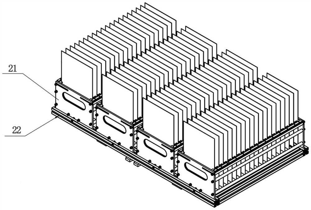
[0086] See attached Figure 3-4 , this embodiment provides a material holding mechanism for a plate processing center, including the positioning device 1 in the embodiment 1, and the material trough 2 . The trough 2 is matched with the positioning device 1 in the first embodiment.

[0087] The chute 2 includes a chute box 21 for holding plates, a tray 22 for receiving the chute box 21, a slide rail 23 is detachably installed on the machine tool of the plate processing center, and the tray 22 is installed on on the slide rail 23 and can slide left and right along the slide rail 23 .

[0088] The tray 22 is a frame-shaped space surrounded by a plurality of aluminum profiles, and a circular positioning rod 24 is arranged in the frame-shaped space for positioning the material chute box 21 in the left and right directions shown in the accompanying drawings. The tank box 21 is placed in the frame-shaped space.

[0089] The tray 22 is also provided with a drive block 25, the chute...

Embodiment 3

[0092] In order to facilitate the understanding of the technical solution in this embodiment, refer to the accompanying drawings, and take the operator standing in front of the machining center to face the angle of view of the machining head as a benchmark, define the X, Y, and Z axes as the Cartesian coordinate system, and the extension direction of the X axis as left and right Horizontally, the left side of the operator is the left side of the machining center, and the right side of the operator is the right side of the machining center; the extension direction of the Y axis is the front and rear longitudinal direction, the side close to the operator is the front side of the machining center, and the side away from the operator The side is the rear side of the machining center; the extension direction of the Z axis is vertical up and down.

[0093] See attached Figure 5-6 , the embodiment of the present invention provides a plate processing center, in addition to including ...


PUM


Abstract

The invention discloses a plate positioning device, a material containing mechanism, a plate machining center and a machining method. The plate positioning device comprises a plate positioning devicebody used for vertically positioning plates and a material groove of the plate machining center, the machining center comprises a rotating mechanism, a first driving mechanism used for bearing the rotating mechanism to move in the Y-axis direction and the Z-axis direction relative to a machine tool, a machining head and a workbench, and a second driving mechanism used for driving the machining head to move; and the rotating mechanism comprises a mechanical arm, the first driving mechanism drives a mechanical arm of the rotating mechanism to position the to-be-machined plates perpendicular to the machine tool and then place the to-be-machined plates into the workbench. The plate positioning device body is vertically arranged, so that the plates are positioned in the vertical direction, thearea occupied by the positioning device in the machining center is effectively reduced, and the production efficiency of the whole machine is improved.

Description

technical field [0001] The invention relates to the field of automatic loading and unloading of plate processing, in particular to a plate positioning device, a material holding mechanism, a processing center and a processing method. Background technique [0002] 3C industries (Computer, Communication, and Consumer Electronics) generally use CNC machine tools for grinding and milling of glass plates. Before CNC machine tools process plate workpieces, the blanks must be accurately positioned to ensure Its machining accuracy. [0003] In the field of plate processing, the workpiece blank is generally transferred from the trough to the fixture by manipulators or manually, and the workpiece is positioned and clamped with the fixture to start processing. Such as Chinese patent ZL201620545086.0, Chinese patent ZL201810004889.9. [0004] ZL201620545086.0 discloses a processing positioning device, including a V-shaped push mechanism to push the plate to move horizontally, a V-shap...

Claims


Application Information

Patent Timeline
IPC IPC(8): B23Q3/18B23Q7/00
CPCB23Q3/18B23Q7/00
Inventor 陆平郑健雄罗杨罗带明赵淑媛肖衍盛
Owner 全准数控设备(苏州)有限公司
Why Eureka
Try Eureka