
Silicon wafer grinding disc correction device and correction process

A technology for grinding discs and silicon wafers, applied in grinding/polishing equipment, metal processing equipment, manufacturing tools, etc., can solve the problems of low precision of grinding correction equipment, reduction of grinding fluid, heavy pollution, etc., to avoid energy consumption, reduce Use, solve the effect of low precision

Active Publication Date: 2020-10-13
ZHEJIANG COWIN ELECTRONICS
View PDF7 Cites 5 Cited by
  • Summary
  • Abstract
  • Description
  • Claims
  • Application Information

AI Technical Summary

Problems solved by technology

[0006] In view of the above problems, the present invention provides a silicon wafer grinding disc correction equipment and its correction process. By setting a back-spray mechanism on the correction wheel, the back-spray mechanism is used to attract the grinding between the upper grinding disc system and the lower grinding disc system. The liquid is recovered and then sprayed for use, fully ensuring the uniform distribution of the grinding liquid between the upper grinding disc system and the lower grinding disc system, improving the grinding effect while reducing the use of grinding liquid, and solving the problem of low precision and poor efficiency of the existing grinding correction equipment. polluting technical issues

Method used


Image

  • Silicon wafer grinding disc correction device and correction process
  • Silicon wafer grinding disc correction device and correction process
  • Silicon wafer grinding disc correction device and correction process

Examples


Embodiment 1

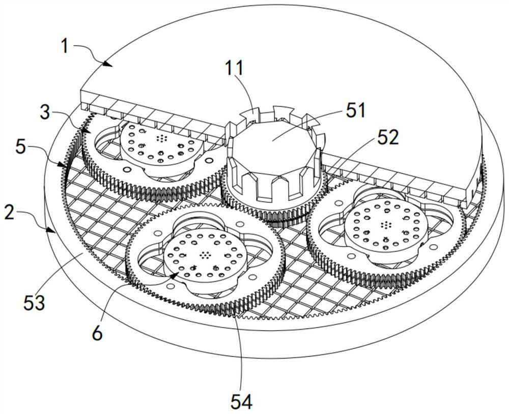
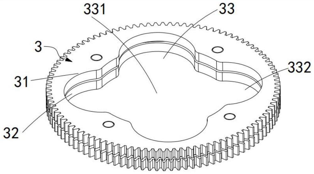
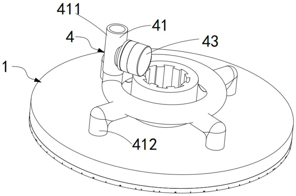
[0067] Such as Figure 1-7 and Figure 9 As shown, a silicon wafer grinding disc correction device includes an upper grinding disc system 1 coaxially arranged, a lower grinding disc system 2 and several dressing wheels arranged between the upper grinding disc system 1 and the lower grinding disc system 2 3. The upper grinding disc system 1 and the lower grinding disc system 2 rotate in opposite directions, the upper grinding disc system 1 is provided with a liquid supply system 4 for supplying grinding fluid, the lower grinding disc system 2 and the A planetary gear linkage system 5 is arranged between the dressing wheels 3. While the dressing wheel 3 revolves around the central axis of the lower grinding disc system 2 through the planetary gear linkage system 5, the dressing wheel 3 revolves around its own central axis. axis rotation;

[0068] The dressing wheel 3 is composed of an upper dressing disc 31 and a lower dressing disc 32 stacked and overlapped. A gap 33 is arran...

Embodiment 2

[0104] Referring to the first embodiment of the present invention, a silicon wafer grinding disc correction process according to the second embodiment of the present invention will be described. :

[0105] Such as Figure 13 As shown, a silicon wafer grinding disc correction process includes the following steps:

[0106] Step 1, cleaning, spray cleaning liquid on the upper grinding disc system 1 and the lower grinding disc system 2 before trimming, to clean and moisten the working environment;

[0107] Step 2, dressing wheel top loading: take 4 sets of dressing wheels 3 with the same specifications and install them on the lower grinding disc system 2, so that the planetary gear 54 on the dressing wheel 3 is respectively connected to the sun gear 52 and the sun gear on the central spindle 51. The ring gear 53 on the outer circumference of the lower grinding disc system 2 is engaged;

[0108] Step 3, install the backspray system, synchronized with step 2, during the process o...


PUM


Abstract

The invention relates to the field of silicon wafer grinding device correction machining, in particular to a silicon wafer grinding disc correction device and correction process. The device comprisesan upper grinding disc system, a lower grinding disc system and a plurality of correction wheels arranged between the upper grinding disc system and the lower grinding disc system, and recycling and spraying mechanisms are arranged on the central notches of the correction wheels. The recycling and spraying mechanisms are arranged on the correction wheels, a grinding liquid between the upper grinding disc system and the lower grinding disc system is recycled and then sprayed and utilized through the recycling and spraying mechanisms, grinding liquid distribution between the upper grinding discsystem and the lower grinding disc system is sufficiently guaranteed to be uniform, use of the grinding liquid is reduced while the grinding effect is improved, and the technical problems of low precision, poor efficiency and heavy pollution of an existing grinding correction device are solved.

Description

technical field [0001] The invention relates to the field of correction processing of silicon wafer grinding equipment, in particular to a silicon wafer grinding disc correction equipment and a correction process thereof. Background technique [0002] Silicon wafer grinding is one of the important processes in silicon wafer processing. Generally, double-sided grinding is used. The main function is to remove tool marks on the surface of silicon wafers, correct thickness deviation, improve flatness, and obtain a uniform surface damage layer; the main principle is The silicon wafer is placed between the upper and lower very flat grinding discs and a certain pressure is applied. When the grinding fluid is added, the grinding disc and the silicon wafer are relatively moved to complete the micro-cutting of the silicon wafer surface. [0003] The silicon wafer grinding disc is made of hard nodular cast iron. It is a forming tool for grinding the surface and a carrier for abrasives....

Claims


Application Information

Patent Timeline
Patent Type & Authority Applications(China)
IPC IPC(8): B24B53/017B24B57/02
CPCB24B53/017B24B57/02
Inventor 郭兵健吴晓峰何国君刘小磐
Owner ZHEJIANG COWIN ELECTRONICS
Learn More