Inducer for high-speed centrifugal pump and working method thereof

A high-speed centrifugal and inducer technology, which is applied in the field of inducers, can solve the problems that the inducer cannot meet the stability of the liquid flow at the inducer outlet at the same time, and achieve the effects of improving internal flow conditions, increasing the outlet head, and reducing wake vortices

Active Publication Date: 2020-10-13
ZHEJIANG SCI-TECH UNIV
View PDF8 Cites 0 Cited by
  • Summary
  • Abstract
  • Description
  • Claims
  • Application Information

AI Technical Summary

Problems solved by technology

[0004] The purpose of the present invention is to design a new type of inducer for high-speed centrifugal pump and its working method in view of the fact that the traditional inducer cannot simultaneously meet the requirements of the stability of the liquid flow at the outlet of the inducer and the lift of the outlet of the inducer to meet the inlet of the impeller.

Method used


Image

  • Inducer for high-speed centrifugal pump and working method thereof
  • Inducer for high-speed centrifugal pump and working method thereof
  • Inducer for high-speed centrifugal pump and working method thereof

Examples


Embodiment Construction

[0021] The present invention will be further described below in conjunction with accompanying drawing.

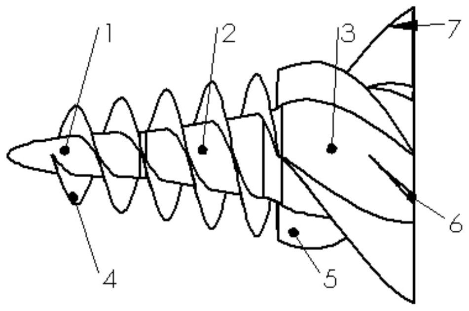
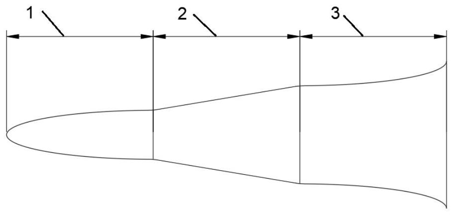
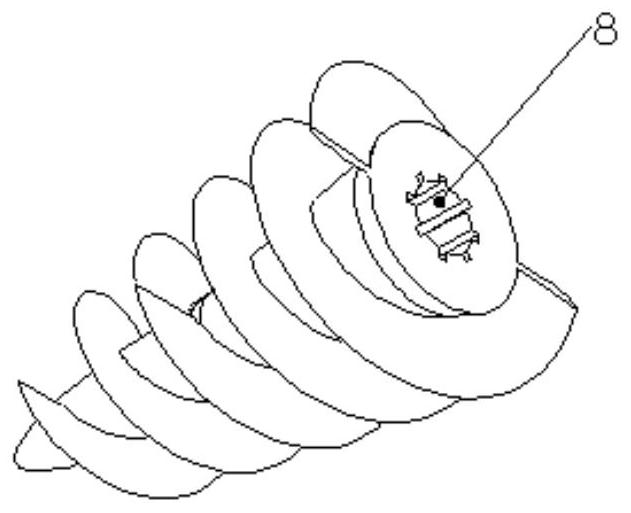
[0022] Such as figure 1 , 2 As shown in and 5, an inducer for a high-speed centrifugal pump is composed of a nonlinear variable curvature hub one 1, a linear hub two 2, a nonlinear variable curvature hub three 3, a main blade 4, a long tail splitter blade 5 and a short tail splitter blade 6 components; the nonlinear variable curvature hub 1 and the linear hub 2 2 are integrally formed; the linear hub 2 2 and the nonlinear variable curvature hub 3 3 are fixed; the nonlinear variable curvature hub 1 is based on a quarter convex ellipse The rotating body whose generatrix and curvature radius gradually increases along the direction from the nonlinear variable curvature hub 1 to the linear hub 2 2, the linear hub 2 2 is a rotating body with the oblique line as the generatrix, and the nonlinear variable curvature hub 3 3 is a quarter A rotating body whose inner concave ellipse ...


PUM


Abstract

The invention discloses an inducer for a high-speed centrifugal pump and a working method thereof. According to a traditional inducer, stable liquid flow at an outlet of the inducer cannot be achieved, and inducer outlet lift cannot meet the requirement of an impeller inlet. A first nonlinear variable-curvature hub is a rotating body with a quarter convex ellipse as a generatrix and the curvatureradius gradually increasing along the direction from the first nonlinear variable-curvature hub to a second linear hub, the second linear hub is a rotating body with an oblique line as a generatrix, and a third nonlinear variable-curvature hub is a rotating body with a quarter concave ellipse as a generatrix and the curvature radius gradually decreasing in the direction from the first nonlinear variable-curvature hub to the second linear hub; main blades are fixed on the first nonlinear variable-curvature hub and the second linear hub; and the third nonlinear variable-curvature hub is fixedlyprovided with four tail long flow dividing blades uniformly distributed along the circumferential direction and four tail short flow dividing blades uniformly distributed in the circumferential direction. The dual functions of stabilizing the outlet liquid flow and increasing the outlet lift are achieved.

Description

technical field [0001] The invention belongs to the field of fluid machinery, and in particular relates to an inducer for reducing the cavitation phenomenon of a high-speed centrifugal pump and a working method thereof. Background technique [0002] High-speed centrifugal pumps are widely used in oil refining, petrochemical, chemical industry and aerospace technology and other fields. However, high-speed centrifugal pumps are prone to cavitation during operation. The cavitation phenomenon has a great impact on the performance of the centrifugal pump. Cavitation can cause spots and cracks on the surface of the blade, and even gradually fall off in a spongy shape; when cavitation occurs, noise will be emitted, which will cause the pump body to vibrate; cavitation When the phenomenon is serious, it can lead to complete inability to output liquid. [0003] At present, the inducer is one of the most effective methods to improve the cavitation performance of centrifugal pumps. I...

Claims


Application Information

Patent Timeline
IPC IPC(8): F04D29/22F04D29/66
CPCF04D29/225F04D29/669
Inventor 陈小平王少龙刘正锋匡仁飞薛凯欣杨徽
Owner ZHEJIANG SCI-TECH UNIV
Why Eureka
Try Eureka