Cylindrical roller bearing and retainer thereof

A cylindrical roller bearing and cage technology, applied in the direction of roller bearings, bearing components, shafts and bearings, can solve the problems of shortening the life of cylindrical roller bearings and easy roller slippage, so as to improve slippage and improve motion. Stability, improve the effect of motion stability

Inactive Publication Date: 2020-10-13
HENAN UNIV OF SCI & TECH
View PDF21 Cites 5 Cited by
  • Summary
  • Abstract
  • Description
  • Claims
  • Application Information

AI Technical Summary

Problems solved by technology

[0004] The object of the present invention is to provide a cage for cylindrical roller bearings to solve the technical problem that the rollers are easy to slip when the cylindrical roller bearings rotate and shorten the life of the cylindrical roller bearings in the prior art; Cylindrical roller bearings for frames to solve the above technical problems

Method used


Image

  • Cylindrical roller bearing and retainer thereof
  • Cylindrical roller bearing and retainer thereof
  • Cylindrical roller bearing and retainer thereof

Examples


specific Embodiment 1

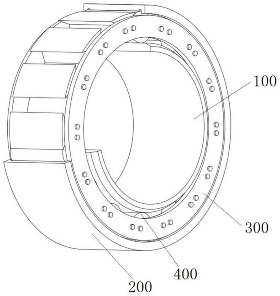
[0052] Such as Figure 1 to Figure 9 As shown, the cylindrical roller bearing includes an inner ring 100, an outer ring 200, and a cage 300. The cage 300 is located between the inner ring 100 and the outer ring 200. The cage 300 is provided with multiple holes uniformly distributed along the circumferential direction of the cylindrical roller bearing. Each pocket 32 ​​is provided with a roller 400 in each pocket 32.

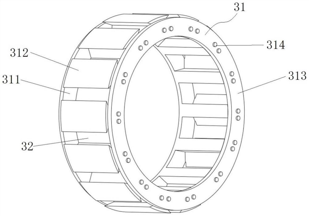
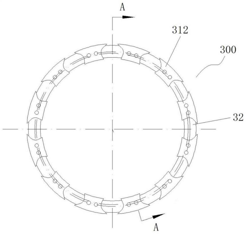
[0053] Such as Figure 2 to Figure 5 As shown, the cage comprises an annular body 31 comprising a first support ring 311 , a web 312 and a second support ring 313 . In this embodiment, each bridge 312 forms a middle section between the first supporting ring 311 and the second supporting ring 313 . Such as Figure 4 As shown, in this embodiment, both the first support ring 311 and the second support ring 313 are fixedly installed separately from the lintel 312 . And by Figure 4 It can be seen from the figure that the outer diameters of the first support ring...

Embodiment 1

[0066] In Embodiment 1, the two support rings are arranged separately from the lintel. Such as Figure 10 and Figure 11 As shown, the difference from Embodiment 1 is that in this embodiment, the first support ring 53 and the lintel 51 are integrally formed, and the second support ring 54 is separately fixed and installed on the lintel 51 and the first support by rivets 55. on ring 53. Wherein, the outer diameters of the first support ring 53 and the second support ring 54 are still smaller than the outer diameter of the intermediate section formed by the cross beams 51 , and outer annular steps 56 are formed outside the two axial ends of the cage 500 . The structure of the pocket 52 is consistent with that in Embodiment 1.

[0067] In this embodiment, in order to fit the outer ring with outer ring ribs on the outside of the cage 500, the outer ring is arranged separately. Specifically, the outer ring includes a straight cylinder and outer ring ribs arranged at both ends of...

specific Embodiment 3

[0069] In Example 1, the designed clearance between the roller and each inclined surface is smaller than the guide clearance between the cage and the inner and outer rings. In this embodiment, the design gap may be larger than the guide gap between the cage and the inner and outer rings.


PUM


Abstract

The invention relates to a cylindrical roller bearing and a retainer thereof. The retainer comprises an annular body. Multiple pocket holes distributed in the circumferential direction are formed in the annular body, the rotating direction of the retainer is defined from back to front, and the pocket holes comprise rear side walls and front side walls. The rear side walls are V-shaped side walls,and the rear side walls comprise rear side wall inner inclined surfaces and rear side wall outer inclined surfaces which are sequentially arranged in the radial direction of the retainer from inside to outside. The rear side wall inner inclined surfaces are inclined backwards from inside to outside, the rear side wall outer inclined surfaces are inclined forwards from inside to outside, and the rear side wall inner and outer inclined surfaces are arranged in a V-shaped crossed manner in order to position a roller. The roller is positioned at an ideal radial position through the V-shaped side walls, the centrifugal motion trend of the roller is restrained, large contact force is still kept between the roller and an inner ring, the slip degree of the roller is reduced, and the slip conditionof the roller is effectively improved. The retainer can be radially positioned by the roller through the V-shaped side walls, the vortex motion radius of the retainer is reduced, and the motion stability of the retainer is improved.

Description

technical field [0001] The invention relates to a cylindrical roller bearing and its cage. Background technique [0002] The main shaft cylindrical roller bearings of aero-engines usually work at high speeds (currently the DN value has reached 3×10 6 mm·r / min or more) working conditions. Existing cylindrical roller bearings, as shown in the Chinese invention patent with the authorized announcement number CN101910660B, the cylindrical roller bearing includes an inner ring, an outer ring and a cage arranged between the inner ring and the outer ring, and the cage is evenly distributed with A plurality of pockets, cylindrical rollers are installed in the pockets and in contact with the inner and outer rings, and the front and rear side walls in the rotation direction of the pockets limit the cylindrical rollers in the circumferential direction. When working, the rotation of the inner ring drives the cylindrical rollers to rotate and revolve, and the cylindrical rollers drive t...

Claims


Application Information

Patent Timeline
Patent Type & Authority Applications(China)
IPC IPC(8): F16C33/46F16C33/58F16C19/22
CPCF16C19/22F16C33/46F16C33/4605F16C33/585
Inventor 刘延斌韩秀英桑得雨邓增辉
Owner HENAN UNIV OF SCI & TECH
Why Eureka
Try Eureka