
Driving shaft assembly

A drive shaft and assembly technology, applied in the field of vehicle parts, can solve problems such as unmanufacturability, difficulty in assembly, oil leakage and rupture of the sheath, etc., and achieve the effects of improving driving comfort, ensuring slip performance, and preventing oil leakage and rupture

Inactive Publication Date: 2020-10-13
GREAT WALL MOTOR CO LTD
View PDF8 Cites 0 Cited by
  • Summary
  • Abstract
  • Description
  • Claims
  • Application Information

AI Technical Summary

Problems solved by technology

[0003] 1. The existing drive shaft products all adopt the form of one-end moving joint or two-end moving joint. The sliding stroke provided by one-end moving joint is short, while the two-end moving joint can provide longer sliding stroke, but Drive shaft swivel performance reduced
[0004] 2. The existing drive shaft assembly anti-detachment structure can be roughly divided into two types. One is to install a circlip at the spline position of the moving joint. Although this method can effectively prevent the drive shaft from detaching from the transmission, it is difficult to disassemble and assemble. Especially the assembly is difficult, often the assembly is not in place, and it is not easy to detect, and the problems frequently occur after the market; the other is to install springs. Although it can effectively solve the problems of prolapse and assembly, the springs are installed inside the mobile joint. , sacrificing the sliding stroke of the drive shaft, it is only applicable to a small number of models
[0005] 3. With the existing drive shaft structure, when the swing angle or sliding function is realized, the sheath will fail such as oil leakage and rupture
[0006] 4. The existing drive shaft structure, in terms of realizing the large swing angle function, is realized by a fixed joint with 8 steel balls at one end and a movable joint at the other end. Although this structure can improve the swing angle performance, it is only better than the traditional The structure is improved by about 5°, but it still cannot meet the requirements of vehicles with high angle requirements, such as vehicles with chassis lifting function or strong off-road performance.
Due to the limited technology and processing level in China, this kind of structure cannot be produced, and the high cost of import and use makes it impossible for domestic vehicles to use this type of product

Method used


Image

  • Driving shaft assembly
  • Driving shaft assembly
  • Driving shaft assembly

Examples


Embodiment Construction

[0042] It should be noted that, in the case of no conflict, the embodiments of the present invention and the features in the embodiments can be combined with each other.

[0043] In the description of the present invention, it should be noted that the orientation or positional relationship indicated by the terms "left", "right", etc. is based on the orientation or positional relationship shown in the drawings, and is only for the convenience of describing the present invention and simplifying the description. It is not intended to indicate or imply that the referred device or element must have a particular orientation, be constructed in a particular orientation, and operate in a particular orientation, and thus should not be construed as limiting the invention.

[0044] The present invention will be described in detail below with reference to the accompanying drawings and examples.

[0045] This embodiment relates to a drive shaft assembly, which mainly includes a shaft body, ...


PUM


Abstract

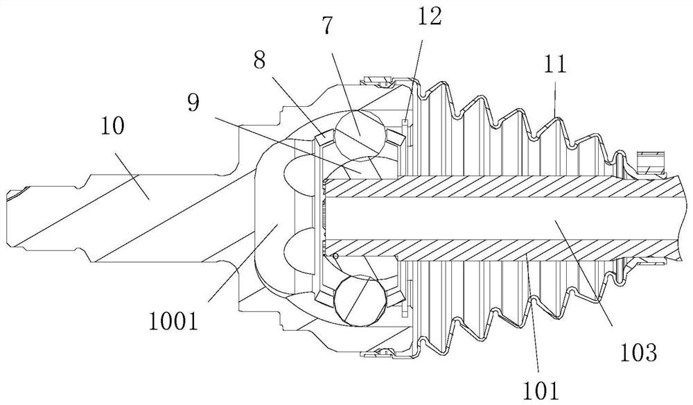
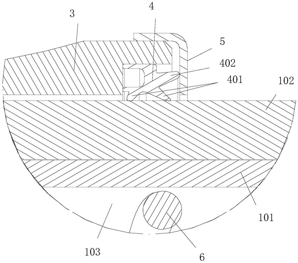
The invention provides a driving shaft assembly which comprises a shaft body; the shaft body comprises a left half shaft and a right half shaft; the left half shaft and the right half shaft slide relatively in the axial direction of the shaft body; two cavities are formed in the left half shaft and the right half shaft in a manner of penetrating through the axial direction and communicate with each other; fixed type constant velocity universal joints are arranged on the left half shaft and the right half shaft; an accommodating cavity communicating with the cavity of the left half shaft or theright half shaft is formed in each of the fixed type constant velocity universal joints; the driving shaft assembly further comprises a sealing structure; the sealing structure comprises a sleeving mounting piece arranged on the connecting part of the left half shaft and the right half shaft in a sleeving manner, and a sealing element arranged between the connecting end of the sleeving mounting piece and the right half shaft. According to the driving shaft assembly, the left half shaft and the right half shaft are in sliding fit to ensure the slippage performance of the driving shaft assembly; the cavities communicate with the accommodating cavities to ensure the air pressure in the two accommodating cavities to be always equal, so that degree resistance generated due to air lock is reduced, and the driving comfort of a vehicle is improved.

Description

technical field [0001] The invention relates to the technical field of vehicle parts, in particular to a drive shaft assembly. Background technique [0002] Drive shaft assembly is the most commonly used component in automobiles, and it is also an indispensable transmission system component assembly. As domestic customers pursue SUV and off-road models, the market share of such models is increasing year by year. Due to the This type of car has a high chassis and a different power arrangement from that of a car, so it has extremely high requirements on the sliding stroke, swing angle and operating environment of the drive shaft assembly. With the improvement of the performance level of this type of vehicle, the products provided by the domestic drive shaft manufacturers have reached their performance limits, so there is an urgent need for a drive shaft product to break through the technical limitations, thereby promoting the further improvement of the vehicle performance leve...

Claims


Application Information

Patent Timeline
IPC IPC(8): F16D3/06F16D3/223F16D3/84B60B35/14
CPCB60B35/14F16D3/06F16D3/223F16D3/84
Inventor 许超楠王强张清华张秀明姚晓东魏俊钮微龙
Owner GREAT WALL MOTOR CO LTD
Learn More