Vehicle hybrid drive arrangement

a hybrid drive and vehicle technology, applied in mechanical equipment, transportation and packaging, gearing, etc., can solve the problems of limiting the driving range and utility of the vehicle, introducing significant weight to the vehicle, and not being able to convert existing internal combustion engine vehicles to hybrid vehicles. achieve the effect of improving maneuverability

Active Publication Date: 2016-07-12
QUANTA PROD LLC
View PDF30 Cites 27 Cited by
  • Summary
  • Abstract
  • Description
  • Claims
  • Application Information

AI Technical Summary

Benefits of technology

[0006]The vehicle hybrid drive arrangement may further comprise a battery system connected to the electric motors/generators, a vehicle sensing and control system, and one or more motor/generator controllers configured to control the electric motors/generators. The arrangement may be configured to operate the electric traction motors/generators as generators to recover energy from a moving vehicle and to store that energy in the battery system and/or to extract energy from the drive wheels to brake or slow a moving vehicle. The secondary power sources may be configured to operate in concert to pivot the vehicle at low speed to improve maneuverability to aid in parking and turning. For example, the arrangement may be configured to supplement power to each drive wheel independently, and/or to operat

Problems solved by technology

Historically, existing internal combustion engine vehicles have not been converted to hybrid vehicles because of the complexity and lack of space to incorporate the electric motors into the drivetrain.
This approach adds significant weight to the vehicle due to the large battery packs and in some cases the large conven

Method used


Image

  • Vehicle hybrid drive arrangement
  • Vehicle hybrid drive arrangement
  • Vehicle hybrid drive arrangement

Examples


example

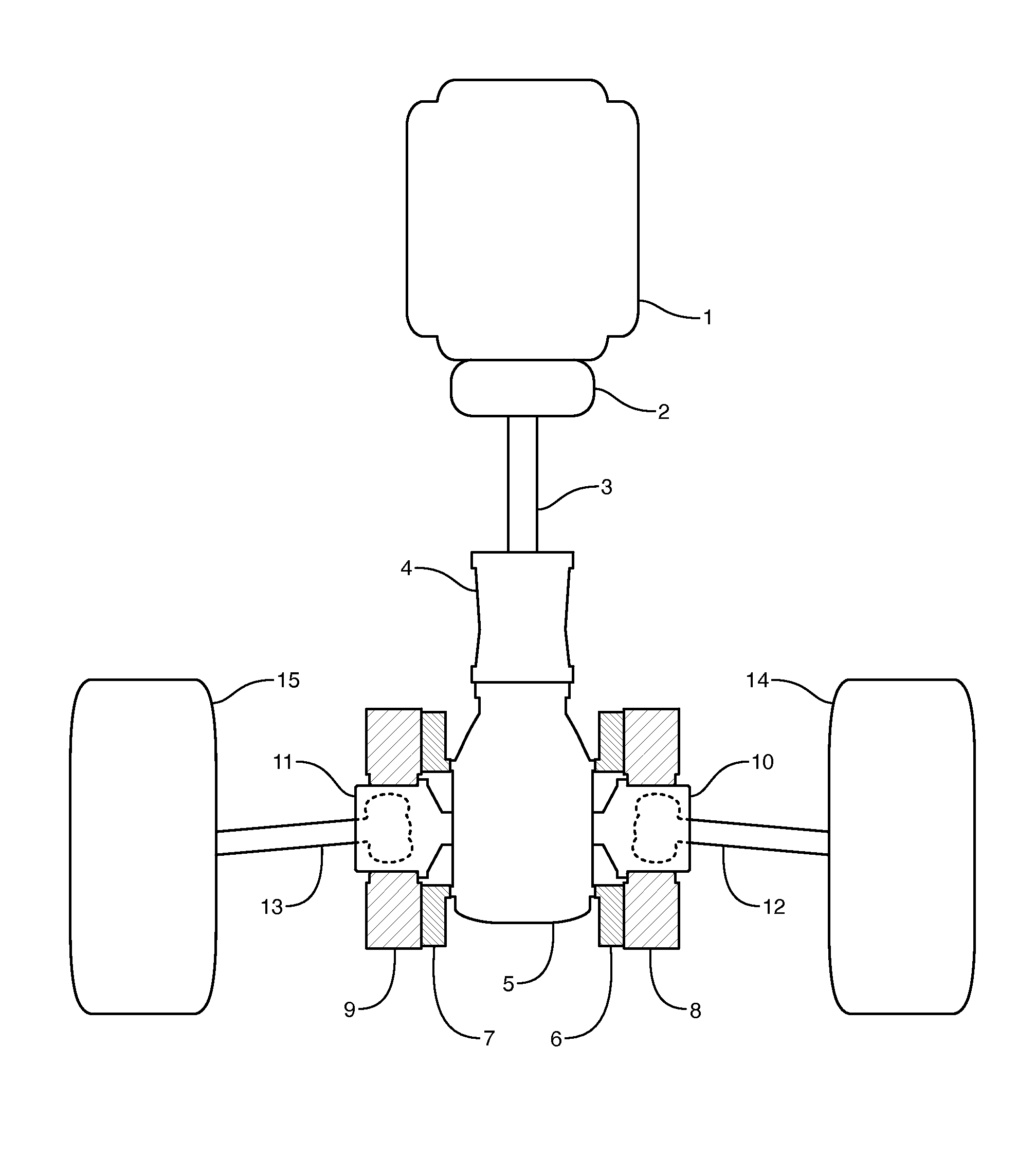
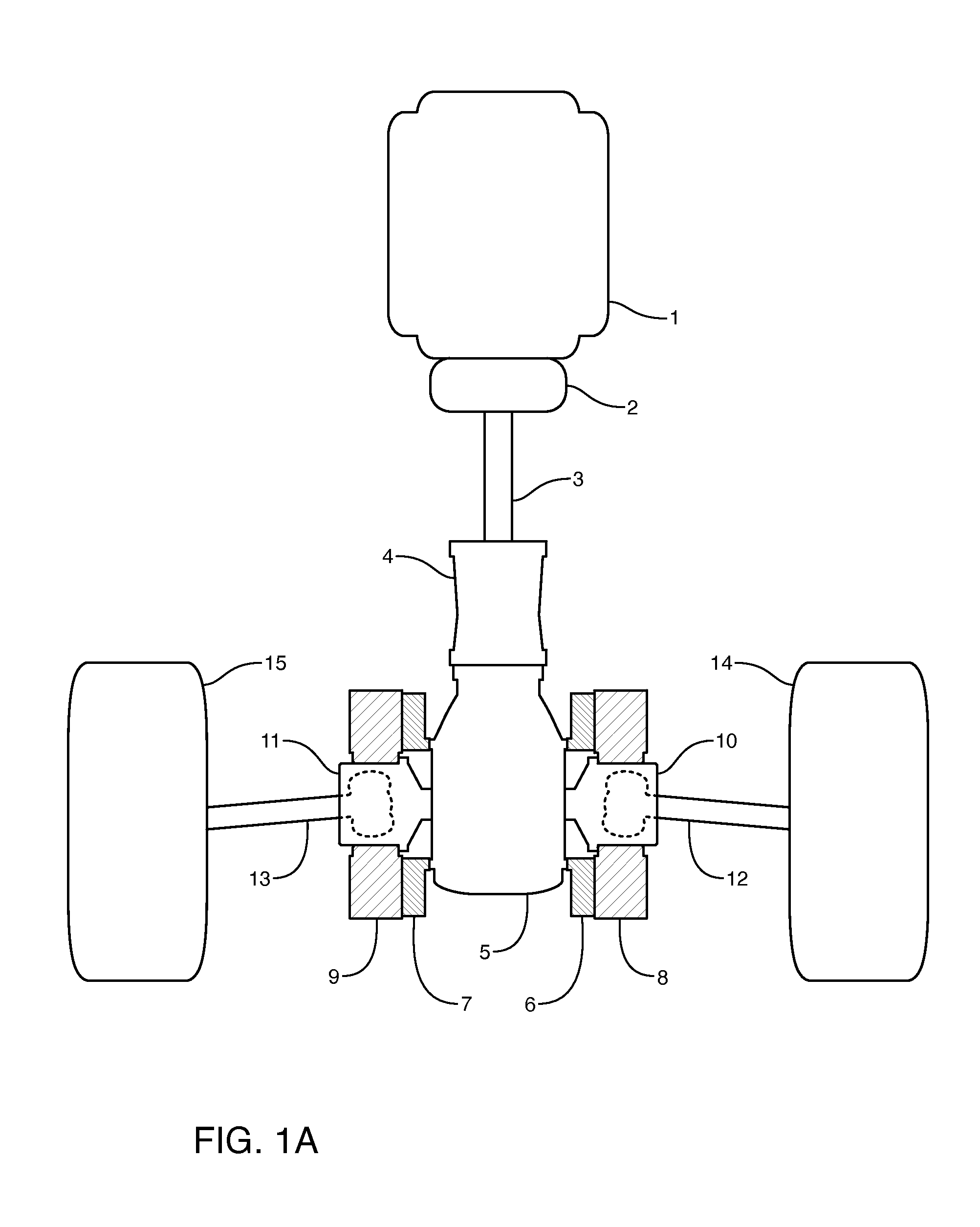
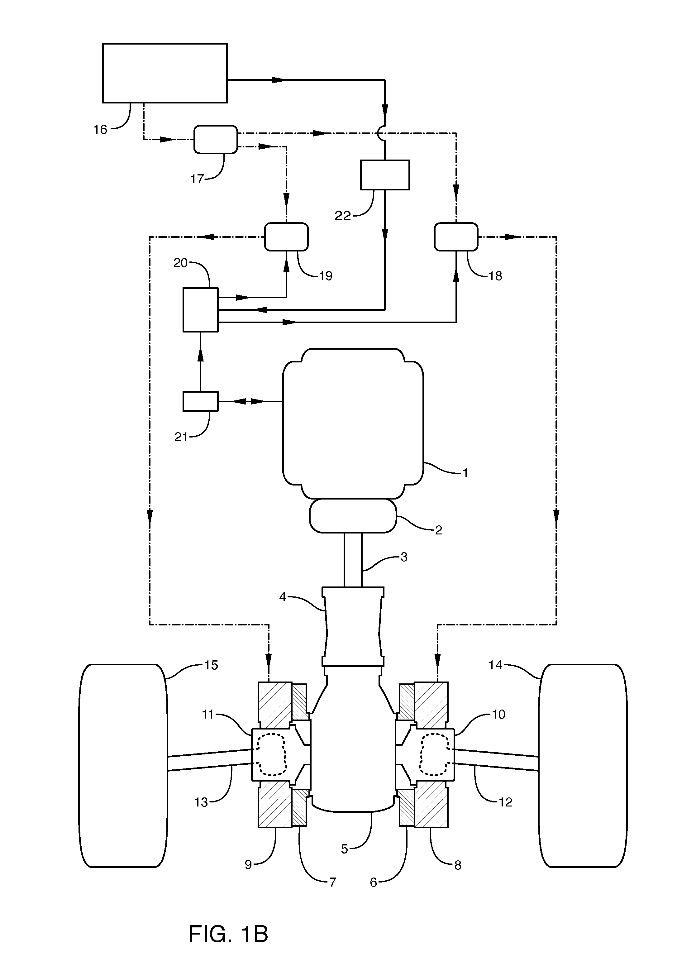
[0057]In certain embodiments, the compact nature of the vehicle hybrid drive arrangement enables retrofitting existing vehicles with limited modifications. In one exemplary embodiment, the vehicle hybrid drive arrangement was installed as a kit in a sixth generation (“C6”) CHEVROLET® CORVETTE® Z06® vehicle. The sixth generation CHEVROLET® CORVETTE® Z06® vehicle possesses a front-mounted internal combustion engine, rear-wheel drive arrangement, with an independent rear suspension. The exemplary CHEVROLET® CORVETTE® Z06® vehicle comprises a clutch, a torque tube, and a manual transmission in the driveline between the engine and the rear differential. The hybrid electric vehicle powertrain kit installed in this example comprised two electric axial flux traction motors / generators; two constant velocity joint coupling devices; two differential case mounting devices; a battery system; two traction motor controllers; and a vehicle sensing and control system. Axial flux electric traction mo...


PUM


Abstract

A hybrid drive arrangement for a motor vehicle comprising two close-coupled electric traction motors/generators on the output of the vehicle differential. A constant velocity joint coupling device is incorporated into the central axis of the traction motors between the differential output shafts and the independent articulated axle shafts for the drive wheels. One embodiment comprises a kit for retrofitting an existing vehicle. The kit comprises two electric traction motors/generators incorporating the constant velocity joint coupling devices, two devices for mounting the traction motors to each side of the differential case between the differential and the independent, articulated axle shafts of the existing vehicle, a battery system electrically coupled to the traction motors, two traction motor controllers, and a vehicle sensing and control system. The arrangement provides for improved acceleration, deceleration, cornering, ease of parking, and fuel economy.

Description

CROSS REFERENCE TO RELATED APPLICATIONS[0001]This application claims priority from U.S. Provisional Patent Application Ser. No. 61 / 898,447, filed Oct. 31, 2013, which is hereby incorporated by reference in its entirety.BACKGROUND OF THE INVENTION[0002]Historically, existing internal combustion engine vehicles have not been converted to hybrid vehicles because of the complexity and lack of space to incorporate the electric motors into the drivetrain. It is desired to be able to convert existing conventional vehicle designs to create hybrid electric vehicles. For example, it is desirable to improve the efficiency and performance of a rear-wheel drive vehicle by retrofitting the mechanical design to include independently controllable electric motors, an energy storage system, motor control units and a supplemental vehicle sensing and control unit. One such conventional design that may benefit from such a retrofit is a front engine, rear drive vehicle, more specifically a front internal...

Claims


Application Information

Patent Timeline
IPC IPC(8): B60K6/52B60W10/08B60K6/445B60W20/00B60K6/365B60W10/26F16H48/06B60K7/00
CPCB60K6/52B60K6/365B60W20/10B60K6/445B60W10/08B60W10/26F16H48/06Y10S903/916Y10S903/91B60K2007/0092B60K2007/0046B60K6/48B60K2006/4808F16H48/36F16H2048/364Y02T10/62
Inventor WHITING, GARY KENWHITING, HILARY PAIGE
Owner QUANTA PROD LLC
Why Eureka
Try Eureka