Constant velocity joint rear wheel suspension system for all-terrain vehicle

a suspension system and constant velocity technology, applied in rigid suspensions, transportation and packaging, cycles, etc., can solve the problems of operator of atv b>90/b> losing control, losing speed, slipping,

Inactive Publication Date: 2009-05-21
STEWART CRAIG
View PDF3 Cites 26 Cited by
  • Summary
  • Abstract
  • Description
  • Claims
  • Application Information

AI Technical Summary

Benefits of technology

[0011]The present invention provides a rear suspension system for an all-terrain vehicle having a chassis and at least three wheels. Two trailing arms are pivotally connected to a chassis. A CV joint pivot arm is pivotally connected to the chassis. A CV joint housing is connected to the CV joint pivot arm. The CV joint housing includes a CV joint bearing. A CV joint is housed inside the CV joint housing and is supported by the CV joint bearing. A drive shaft riding on a drive shaft bearing extends through the CV joint and is rigidly connected to the CV joint. A shock absorption system is connected between the drive shaft and the chassis. In a preferred embodiment, a cross bar is connected between the trailing arms for stability. Also, preferably, the rear suspension system includes a sway bar assembly and linear shock absorbers acting in combination to provide optimum suspension.

Problems solved by technology

However, due to the speed of the ATV and the height of the bump, rear wheel 96 has lost contact with the ground.
The operator of ATV 90 is now in danger of losing control, losing speed or even tipping over and crashing.

Method used


Image

  • Constant velocity joint rear wheel suspension system for all-terrain vehicle
  • Constant velocity joint rear wheel suspension system for all-terrain vehicle
  • Constant velocity joint rear wheel suspension system for all-terrain vehicle

Examples


Embodiment Construction

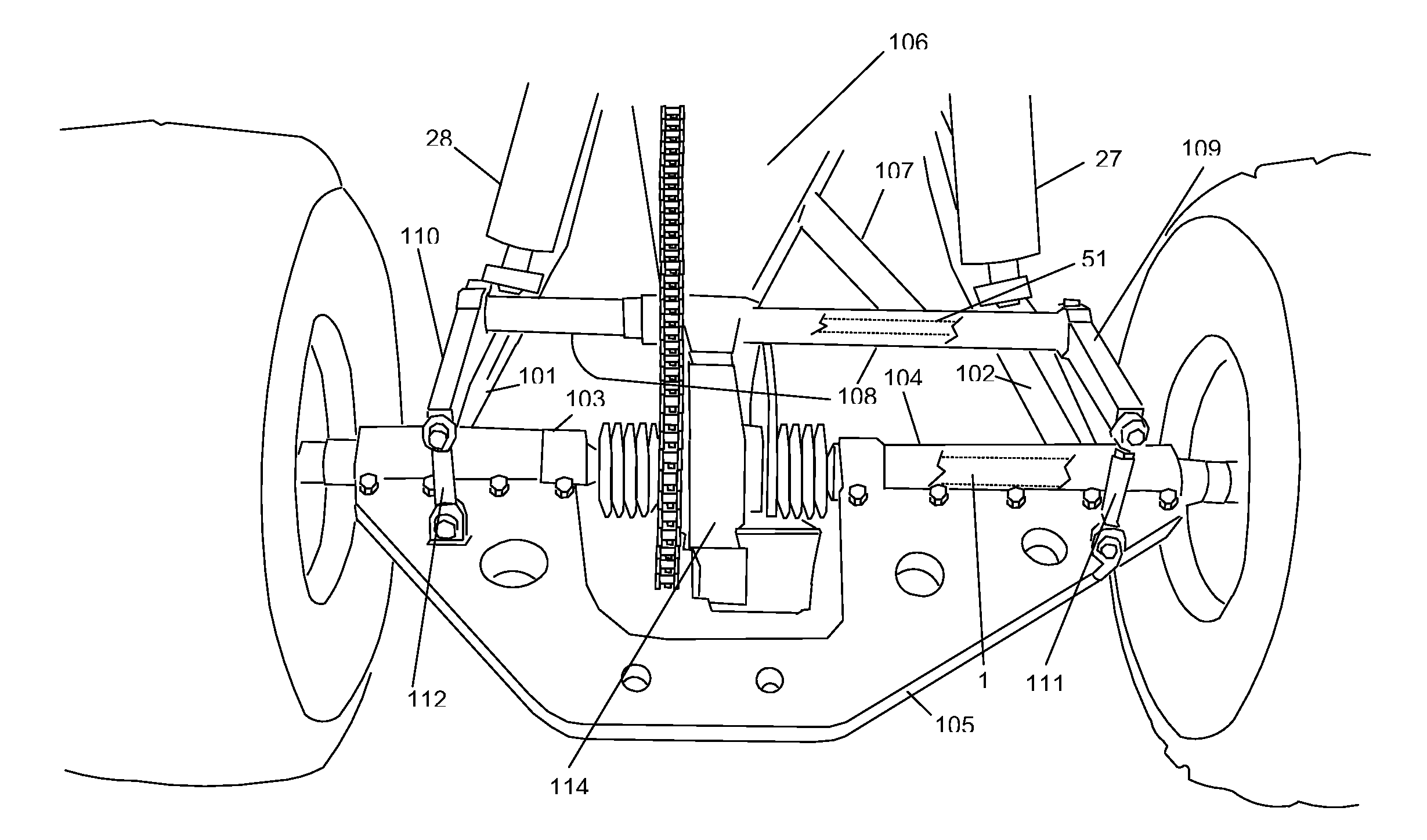
[0020]FIGS. 10, 11, and 13-16 show a preferred embodiment of the present invention. ATV 100 utilizes CV joint 5 (FIGS. 13 and 14) located within CV joint housing 2 to provide optimum rear suspension. CV joint 5 allows for the movement of drive shaft 1 in any direction while ATV 100 is in operation. Therefore, as shown in FIGS. 15 and 16, when ATV 100 hits a bump at high speed, both wheels 31 and 32 will remain in contact with the ground in order to provide optimum control at high speed and safety to the operator.

CV Joint

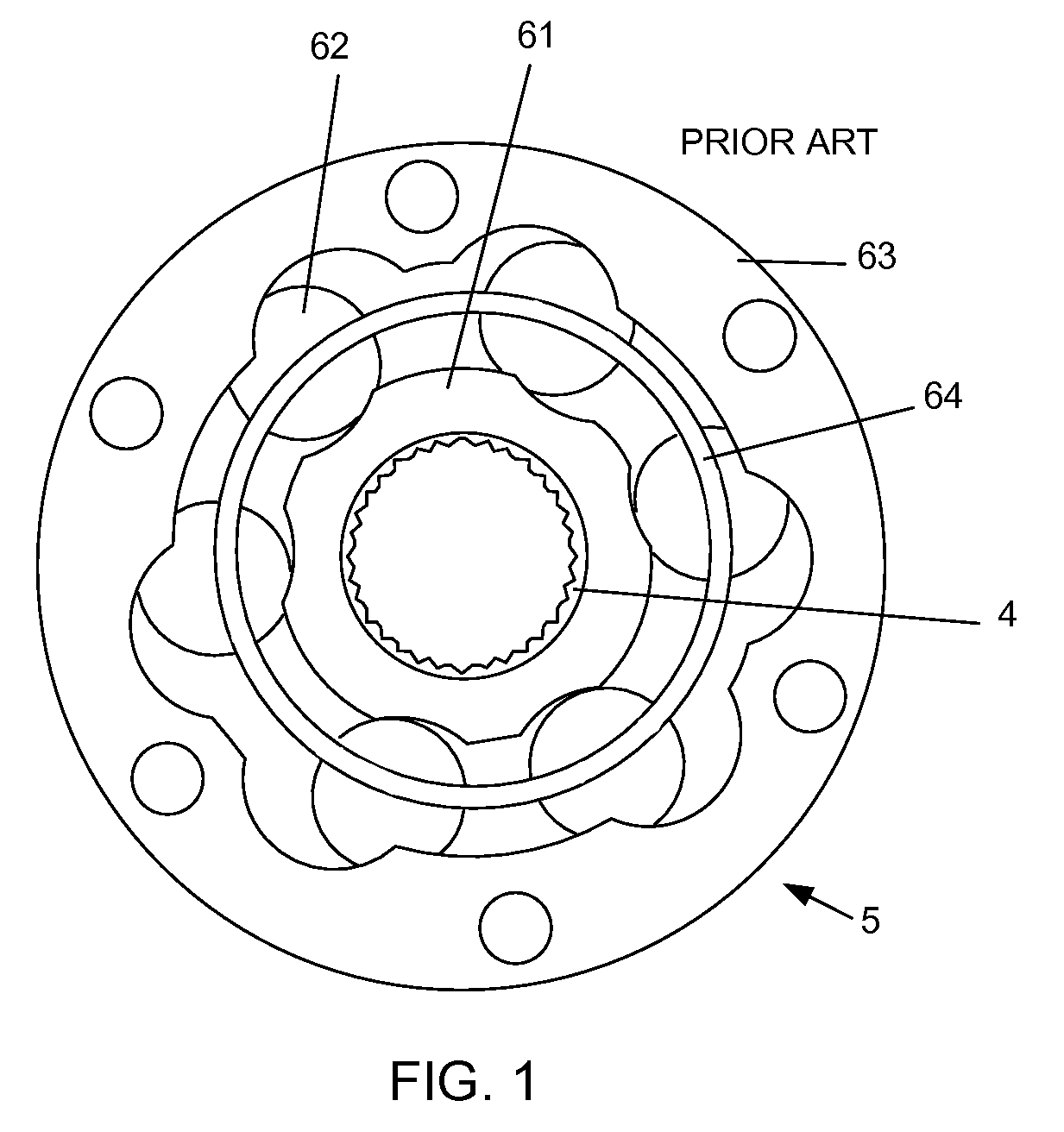
[0021]Drive shaft 1 extends through CV joint housing 2. To prevent slipping, preferably shaft 1 includes splines 3 (FIG. 13) that mesh with splines 4 of CV joint 5. Sprocket drive flange 6 is bolt connected to CV joint 5. Rotor drive flange 7 is also bolt connected to CV joint 5. Likewise, sprocket 8 is bolted to sprocket drive flange 6 and brake rotor 9 is bolted to rotor drive flange 7. CV joint 5 is supported by CV joint bearings 41 and 42.

Chain Drive

[0022]In a pr...


PUM


Abstract

A rear suspension system for an all-terrain vehicle having a chassis and at least three wheels. Two trailing arms are pivotally connected to a chassis. Each of the trailing arms includes a drive shaft bearing. A CV joint pivot arm is pivotally connected to the chassis. A CV joint housing is connected to the CV joint pivot arm. The CV joint housing includes a CV joint bearing. A CV joint is housed inside the CV joint housing and is supported by the CV joint bearing. A drive shaft extends through the CV joint and rigidly connected to the CV joint. The drive shaft is further supported by each of the drive shaft bearings attached to the trailing arms. A shock absorption system is connected between the drive shaft and the chassis. In a preferred embodiment, a cross bar is connected between the trailing arms for stability. Also, preferably, the rear suspension system includes a sway bar and linear shock absorbers acting in combination to provide optimum suspension.

Description

[0001]The present invention relates to all-terrain vehicles, and, in particular, to rear suspension systems for all-terrain vehicles.BACKGROUND OF THE INVENTIONCV Joints[0002]Constant Velocity (CV) joints are known in the prior art. CV joints are commonly attached to automobile axles and they allow the axle to move in all directions, including longitudinal, back-and-forth and up-and-down. The CV joint allows a rotating axle to transmit power through a variable angle, at constant rotational speed, without an appreciable increase in friction or play. The CV joint functions to keep the drive wheels of a vehicle on the ground, while allowing the drive wheels to travel up and down with the suspension.[0003]FIG. 1 shows prior art CV joint 5. CV joint 5 includes splined inner race 61. Splines 4 rigidly connect CV joint 5 to a splined drive shaft so that there is no slippage. Steel balls 62 ride in grooves in inner race 61 and outer race 63. Balls 62 are nested inside holes in circular cage...

Claims


Application Information

Patent Timeline
Patent Type & Authority Applications(United States)
IPC IPC(8): B60G21/055B60G9/00
CPCB62K5/027B62K5/01
Inventor STEWART, CRAIG
Owner STEWART CRAIG
Why Eureka
Try Eureka