
Flat single-shaft series multi-point synchronous driving tracking speed reducer

A synchronous drive, flat single-shaft technology, applied in transmission boxes, electromechanical devices, mechanical equipment, etc., can solve the problems of high speed, low transmission efficiency, low efficiency of synchronous transmission shafts, and achieve space saving, cost saving, and reducing cost effect

Pending Publication Date: 2020-10-13
JIANGYIN HUAFANG NEW ENERGY HIGH TECH EQUIP
View PDF1 Cites 5 Cited by
  • Summary
  • Abstract
  • Description
  • Claims
  • Application Information

AI Technical Summary

Problems solved by technology

[0002] At present, the flat single-axis tracking system is more commonly used in solar photovoltaic tracking applications. In order to solve the shortcomings of flat single-axis single-point drive that is easy to cause drive damage or main beam tube torque damage in the case of strong winds and vibrations, the recent industry trend is more and more More and more manufacturers of tracking brackets have begun to explore the technology of multi-point parallel drive of single main girder
In the flat single-axis multi-point series synchronous drive tracking system, most rotary reducers still have many defects: small transmission torque, low efficiency, interference between external dimensions and on-site installed components, high cost, etc.
The invention patent with the application number 202010188648.1 discloses a flat single-shaft linkage reducer, which not only has low transmission efficiency, but also has a high speed of the synchronous transmission shaft between the reducers due to the roughly transmission ratio, because the transmission shaft is usually 7-8m long, As a result, the transmission rigidity of the system is poor, and failures such as jitter are prone to occur. This makes the reducer on the market currently unable to fully meet the needs of customers in terms of actual use or cost.

Method used


Image

  • Flat single-shaft series multi-point synchronous driving tracking speed reducer
  • Flat single-shaft series multi-point synchronous driving tracking speed reducer
  • Flat single-shaft series multi-point synchronous driving tracking speed reducer

Examples


Embodiment Construction

[0034] The present invention will be further described in detail below in conjunction with the accompanying drawings and embodiments.

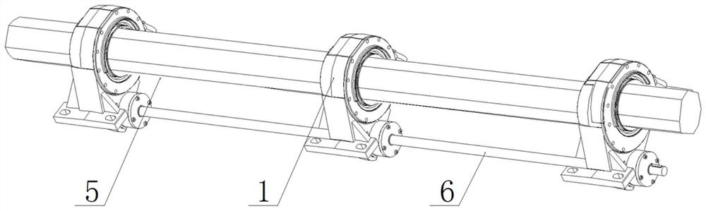
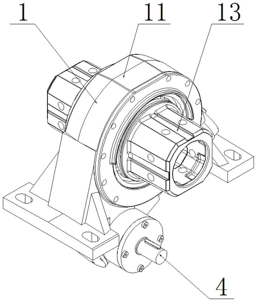
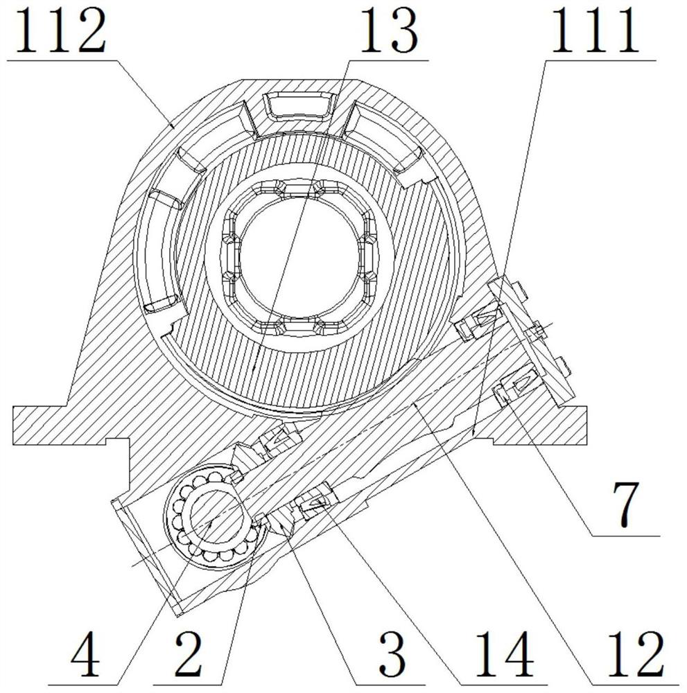
[0035] Such as Figure 1 ~ Figure 3 As shown, a flat single-axis series multi-point synchronous drive tracking reducer in this embodiment includes a plurality of worm gear and worm rotary drive devices 1 arranged at intervals before and after, and the worm gear and worm rotary drive devices 1 include a base 11 , the base 11 includes a shaft housing 111 and a seat ring 112, the shaft housing 111 is provided with a worm 12, the seat ring 112 is provided with a gear shaft 13, the worm 12 is meshed with the gear shaft 13, the One end of the worm 12 is provided with a bevel gear 3 through a lock nut 2, and the base 11 is equipped with a bevel gear shaft 4 at a position close to the bevel gear 3, and the bevel gear shaft 4 is meshed with the bevel gear 3 and is adjacent to the bevel gear 3. A main beam 5 is connected between the gear shafts 13 of t...


PUM


Abstract

The invention relates to a flat single-shaft series multi-point synchronous driving tracking speed reducer. The flat single-shaft series multi-point synchronous driving tracking speed reducer comprises a plurality of worm and gear rotation driving devices (1) arranged left and right at intervals, each worm and gear rotation driving device (1) comprises a base (11), each base (11) comprises a shaftshell (111) and a seat ring (112), a worm (12) is arranged in each shaft shell (111), a gear shaft (13) is arranged in each seat ring (112), the worms (12) are meshed with the gear shafts (13), a bevel gear (3) is arranged at one end of each worm (12), a bevel gear shaft (4) is arranged at the position, close to each bevel gear (3), of each base (11) in a penetrating mode, and the bevel gear shafts (4) are meshed with the bevel gears (3). According to the flat single-shaft series multi-point synchronous driving tracking speed reducer, the worms and the gears are combined with the bevel gear shafts arranged in the bases, and the bevel gear shafts are driven to transmit power through the bevel gears arranged on the worms, so that the worms of the rotary speed reducer are steered, divided and tracked in series.

Description

technical field [0001] The invention relates to a flat single-axis series multi-point synchronous drive tracking reducer, which is mainly used for solar photovoltaic tracking systems, especially a flat single-axis series multi-point synchronous drive tracking bracket. Background technique [0002] At present, the flat single-axis tracking system is more commonly used in solar photovoltaic tracking applications. In order to solve the shortcomings of flat single-axis single-point drive that is easy to cause drive damage or main beam tube torque damage in the case of strong winds and vibrations, the recent industry trend is more and more More and more manufacturers of tracking brackets have begun to explore the technology of multi-point parallel drive of single girder. In the flat single-axis multi-point series synchronous drive tracking system, most slewing reducers still have many defects: small transmission torque, low efficiency, interference between external dimensions and...

Claims


Application Information

Patent Timeline
IPC IPC(8): F16H57/02F16H57/021F16H57/023F16H57/038F16H57/039H02K7/116
CPCF16H57/02F16H57/021F16H57/023F16H57/038F16H57/039F16H2057/02034F16H2057/02069F16H2057/02086H02K7/1166
Inventor 王利华潘苗夏飞
Owner JIANGYIN HUAFANG NEW ENERGY HIGH TECH EQUIP
Features
  • Generate Ideas
  • Intellectual Property
  • Life Sciences
  • Materials
  • Tech Scout
  • Unparalleled Data Quality
  • Higher Quality Content
  • 60% Fewer Hallucinations
Learn More