A birdcage automatic welding device

An automatic welding and birdcage technology, applied in welding equipment, resistance welding equipment, manufacturing tools, etc., can solve the problems of reduced work efficiency, easy soreness, labor, etc., and achieve the effect of high work efficiency

Active Publication Date: 2022-05-17
临沂临港国有资产运营集团有限公司
View PDF9 Cites 0 Cited by
  • Summary
  • Abstract
  • Description
  • Claims
  • Application Information

AI Technical Summary

Problems solved by technology

[0005] In order to overcome the shortcomings that people need to continuously pull the birdcage to drive the wire loop to be completely welded, it takes a long time, it is laborious, and the hand is prone to soreness, resulting in a decrease in follow-up work efficiency. The technical problem of the present invention is: to provide a The wire ring is welded on the birdcage, which saves labor and is an automatic birdcage welding device with high work efficiency

Method used


Image

  • A birdcage automatic welding device
  • A birdcage automatic welding device
  • A birdcage automatic welding device

Examples


Embodiment 1

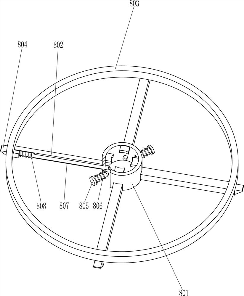
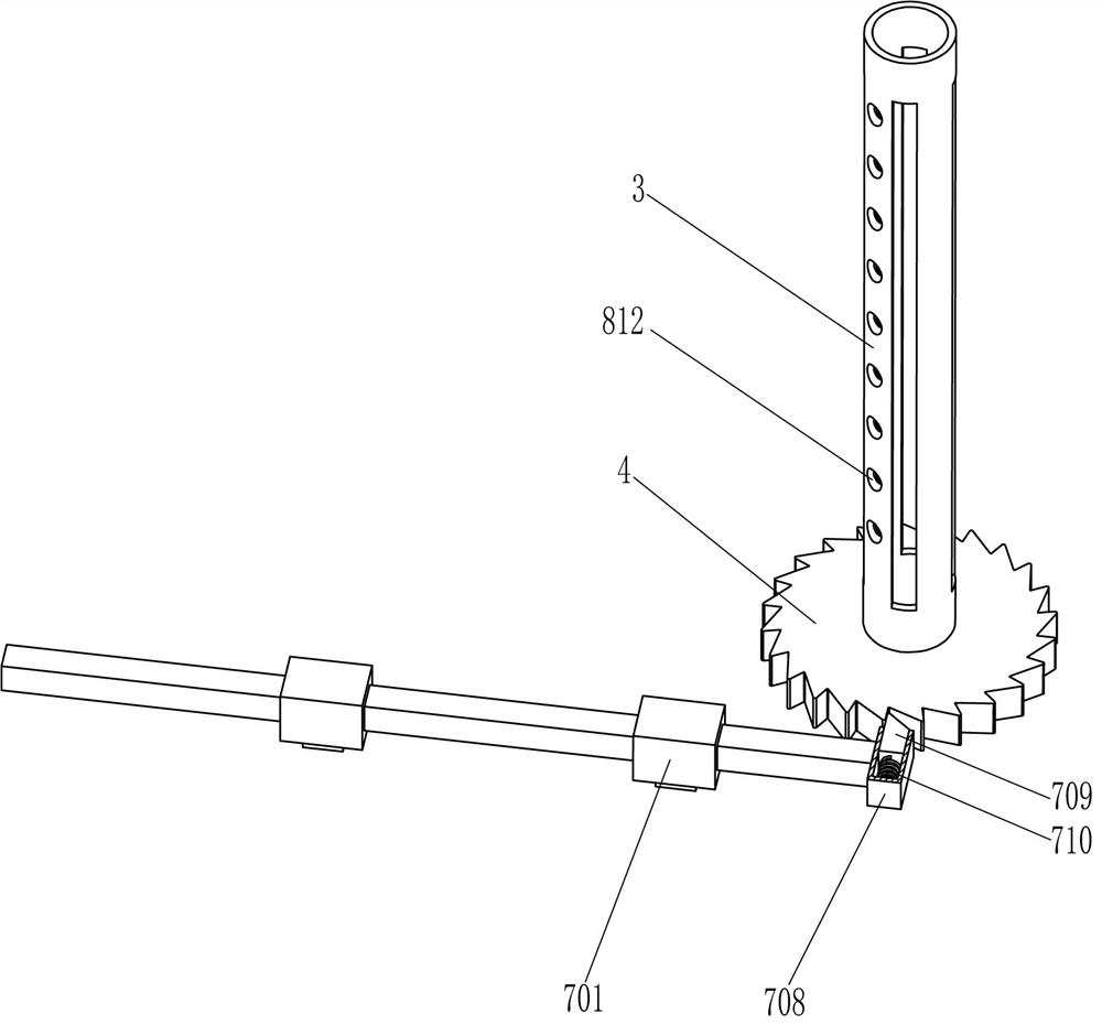
[0025] A birdcage automatic welding device, such as Figure 1-6 As shown, it includes a bottom plate 1, a support frame 2, a hollow shaft 3, a support plate 31, a ratchet 4, a guide sleeve 5, a welding assembly 6, a rotating assembly 7 and a support assembly 8, and the bottom left rear part of the top of the bottom plate 1 is fixed with a support Frame 2, guide sleeves 5 are fixedly connected to the upper, lower, and left sides of the inner rear side of the support frame 2, and a welding assembly 6 is provided between the guide sleeves 5 on the upper and lower sides and the inner side of the support frame 2, and the top right side of the bottom plate 1 is rotated in the middle. The hollow rotating shaft 3 is connected, and the rotating assembly 7 is arranged between the top and the front side of the bottom plate 1. The outer surface of the lower part of the hollow rotating shaft 3 is fixed with a ratchet 4 in the peripheral direction, and the ratchet 4 is in contact with the ro...

Embodiment 2

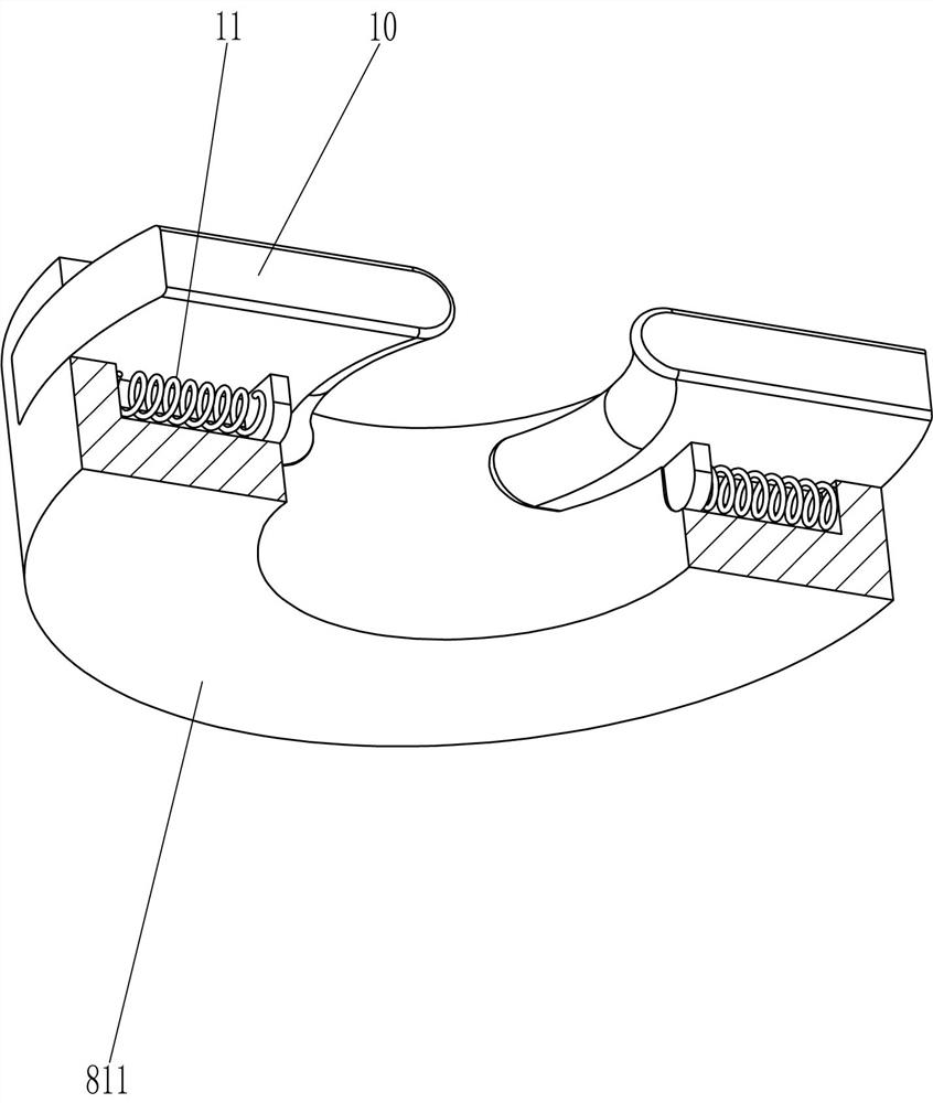
[0034] On the basis of Example 1, such as Figure 7 As shown, it also includes an extrusion block 10 and a ninth spring 11. The front and rear parts of the annular block 811 are slidably connected with the extrusion block 10. The extrusion block 10 cooperates with the special-shaped rod 809, and the inner side of the bottom of the extrusion block 10 A ninth spring 11 is connected with the inside of the ring block 811 .

[0035]When the operator pulls the special-shaped rod 809 to move upward, the upward movement of the special-shaped rod 809 drives the extruding block 10 to move outward, the ninth spring 11 compresses, and the extruding block 10 moves outward to contact the birdcage 9 to fix it. When the birdcage 9 is welded with the wire ring, the birdcage 9 is removed from the support plate 31, the birdcage 9 is separated from the extrusion block 10, and then the operator pushes the special-shaped rod 809 to move downward and reset, because the ninth spring 11 The role of e...


PUM


Abstract

The invention relates to a welding device, in particular to an automatic birdcage welding device. The technical problem is how to design an automatic birdcage welding device that can replace the manual welding of the wire ring on the birdcage, which is labor-saving and has high work efficiency. An automatic birdcage welding device, comprising: a bottom plate, a support frame is fixedly connected to one side of the bottom plate, and a guide sleeve is fixed to the inner side edge position symmetrically; a hollow rotating shaft, the hollow rotating shaft is rotatably connected in the middle of the side of the bottom plate away from the support frame. In the present invention, the unmanufactured bird cage is placed on the support plate, an iron wire loop is placed on the outside of the bird cage to contact the wedge-shaped rod, the butt welding machine is started, and then the servo motor is started to rotate forward, so that the butt welding machine can move The iron wire loop is welded on the birdcage, and by rotating the assembly, the iron wire loop can be completely welded on the birdcage, without the need for people to pull the birdcage.

Description

technical field [0001] The invention relates to a welding device, in particular to an automatic birdcage welding device. Background technique [0002] The birdcage is the main environment for watching birds to carry out activities and inhabit. "If a worker wants to be good at his work, he must first sharpen his tools." Whether the bird-raising utensils are applicable or not is one of the keys to raising a good watching bird. Therefore, only by preparing suitable birdcages and other accessories can the birds be kept healthy and lively, singing freely, and suitable for viewing. According to different body shapes and habits, birdcages are divided into many types. Birdcages are divided into southern birdcages and northern birdcages. The hometown of birdcages in China, Kara in Danzhai, Guizhou - the hometown of birdcages in the south. In Yihezhuang, Zhuozhou, Hebei Province - the hometown of beilong cages, during the production process of birdcages, iron wire rings need to be ...

Claims


Application Information

Patent Timeline
Patent Type & Authority Patents(China)
IPC IPC(8): B23K11/02B23K11/36B21F15/02B21F45/00
CPCB23K11/02B23K11/362B21F15/02B21F45/00
Inventor 不公告发明人
Owner 临沂临港国有资产运营集团有限公司
Why Eureka
Try Eureka