In-tunnel dismantling method for thrust cylinders of shield tunneling machine

A technology for propelling oil cylinders and shield machines, applied in the field of machinery, can solve the problems of small space, large size, and long dismantling time, and achieve the effects of safe operation, avoidance of injury, and easy operation and realization.

Active Publication Date: 2020-10-16
SINOHYDRO ENG BUREAU 4
View PDF5 Cites 0 Cited by
  • Summary
  • Abstract
  • Description
  • Claims
  • Application Information

AI Technical Summary

Problems solved by technology

[0002] The shield machine is a must-use equipment for subway tunnel excavation. After the tunnel construction is completed, due to some special reasons, it cannot slide to the open-air demolition well. The crawler crane or truck crane is used for demolition. The demolition equipment can only be carried out in the cave.
However, due to the small space in the cave, the shield machine itself is not only very large, but also uses many hydraulic cylinders inside, and the dismantling environment is relatively closed, so it is not easy to dismantle. Usually, it is used on the shield inner wall of the shield machine. Welding lugs combined with manual hoists and slings to dismantle the propulsion cylinder. This method can only dismantle a single cylinder at a time, and the removal time is long and the safety cannot be guaranteed. Therefore, the demolition in the hole of the shield machine is the current method of many construction methods. common technical problems

Method used


Image

  • In-tunnel dismantling method for thrust cylinders of shield tunneling machine
  • In-tunnel dismantling method for thrust cylinders of shield tunneling machine
  • In-tunnel dismantling method for thrust cylinders of shield tunneling machine

Examples


Embodiment Construction

[0033] Features and exemplary embodiments of various aspects of the invention will be described in detail below. In the following detailed description, numerous specific details are set forth in order to provide a thorough understanding of the present invention. It will be apparent, however, to one skilled in the art that the present invention may be practiced without some of these specific details. The following description of the embodiments is only to provide a better understanding of the present invention by showing examples of the present invention. The present invention is by no means limited to any specific configurations and algorithms presented below, but covers any modification, substitution and improvement of elements, components and algorithms without departing from the spirit of the invention. In the following description, well-known structures and techniques have not been shown in order to avoid unnecessarily obscuring the present invention.

[0034] Example em...


PUM


Abstract

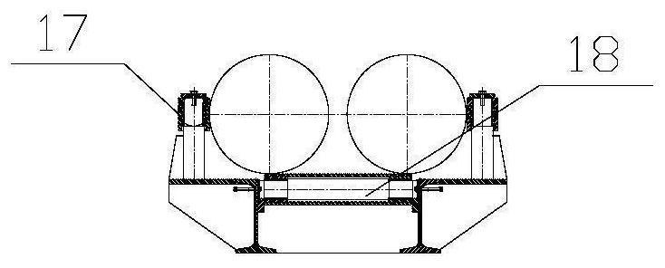
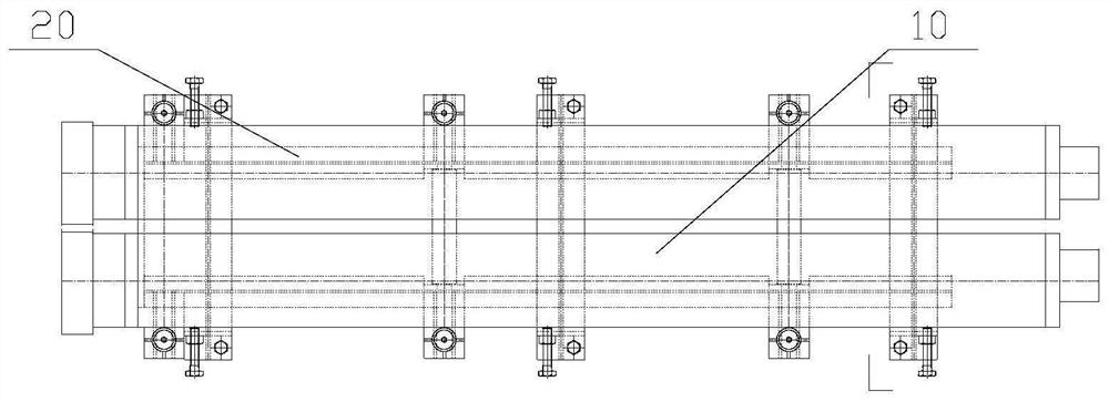
The invention discloses an in-tunnel dismantling method for thrust cylinders of a shield tunneling machine. The in-tunnel dismantling method comprises the steps that a thrust cylinder support is constructed; red and blue oil cylinders are driven to rise, so that the front ends of the thrust cylinder supports are arranged at the lower parts of the outer ends of every two thrust cylinders in one group; the outer ends of the thrust cylinders are fixed to the thrust cylinder support; a segment erector is driven to travel towards the outer side along a traveling beam, and the thrust cylinders are driven to move outwards in the axial direction; after the thrust cylinders are completely dragged out, a thrust cylinder fixing device is fixed again; the red and blue oil cylinders are recovered downwards, so that the thrust cylinders move downwards along with the thrust cylinder support; a swing mechanism, the thrust cylinder support and the thrust cylinders of the segment erector are driven to rotate around the traveling beam of the segment erector; and when the thrust cylinders on the thrust cylinder support rotate to the position below the traveling beam of the segment erector, the thrustcylinders are unloaded on a transportation trolley on a bottom rail. By means of the in-tunnel dismantling method, a set of thrust oil cylinders can be dismantled at a time at the same time, rapid, efficient and safe operation can be achieved, only supports for bearing and fixing the thrust cylinders need to be additionally arranged, and operation and implementation are easier.

Description

technical field [0001] The invention relates to the technical field of machinery, in particular to a method for dismantling a shield machine propulsion cylinder in a hole. Background technique [0002] The shield machine is a necessary equipment for subway tunnel excavation. After the tunnel construction is completed, due to some special reasons, it cannot slide to the open-air demolition shaft for demolition with crawler cranes or truck cranes. The demolition equipment can only be carried out in the cave. However, due to the small space in the cave, the shield machine itself is not only very large, but also uses many hydraulic cylinders inside, and the dismantling environment is relatively closed, so it is not easy to dismantle. Usually, it is used on the shield inner wall of the shield machine. Welding lugs combined with manual hoists and slings to dismantle the propulsion cylinder. This method can only dismantle a single cylinder at a time, and the removal time is long an...

Claims


Application Information

Patent Timeline
Patent Type & Authority Applications(China)
IPC IPC(8): B25B27/00B25B11/00
CPCB25B27/00B25B11/00
Inventor 何京健于建伟刘培玉谭磊郑红焕田光董贤
Owner SINOHYDRO ENG BUREAU 4
Why Eureka
Try Eureka