Integrated envelope eyelet binding machine

A technology for binding machines and envelopes, applied in binding and other directions, can solve the problems of inconvenient rivet insertion, accumulation of positioning errors, and reduced work efficiency, and achieve the effects of strong automation capability, avoiding error accumulation, and improving binding quality.

Active Publication Date: 2020-10-16
瑞安市方大信封机械有限公司
View PDF12 Cites 0 Cited by
  • Summary
  • Abstract
  • Description
  • Claims
  • Application Information

AI Technical Summary

Problems solved by technology

[0002] In the existing envelope binding process, it is necessary to punch holes in the strip-shaped blank material for making eye buttons in advance, then put the rivets into the punched holes, and then press the rivets and strips together to buckle the envelope. In fact, this will gradually accumulate the positioning errors between the rivet placing station and the strip-shaped blank for punching holes, which will easily lead to large nailing errors, resulting in failure of the envelope eye button binding, reducing the binding quality of the envelope, and requiring multiple times. Calibrating the punching mechanism is time-consuming and labor-intensive, which reduces work efficiency. When punching strip-shaped blanks, the waste will easily block the puncher, and the inner wall of the punching hole is not smooth enough to facilitate the smooth insertion of rivets, resulting in punching Poor quality and low yield rate, in view of this, we propose an integrated envelope eye button binding machine

Method used


Image

  • Integrated envelope eyelet binding machine
  • Integrated envelope eyelet binding machine
  • Integrated envelope eyelet binding machine

Examples


Embodiment Construction

[0021] The following will clearly and completely describe the technical solutions in the embodiments of the present invention with reference to the accompanying drawings in the embodiments of the present invention. Obviously, the described embodiments are only some, not all, embodiments of the present invention. Based on the embodiments of the present invention, all other embodiments obtained by persons of ordinary skill in the art without creative efforts fall within the protection scope of the present invention.

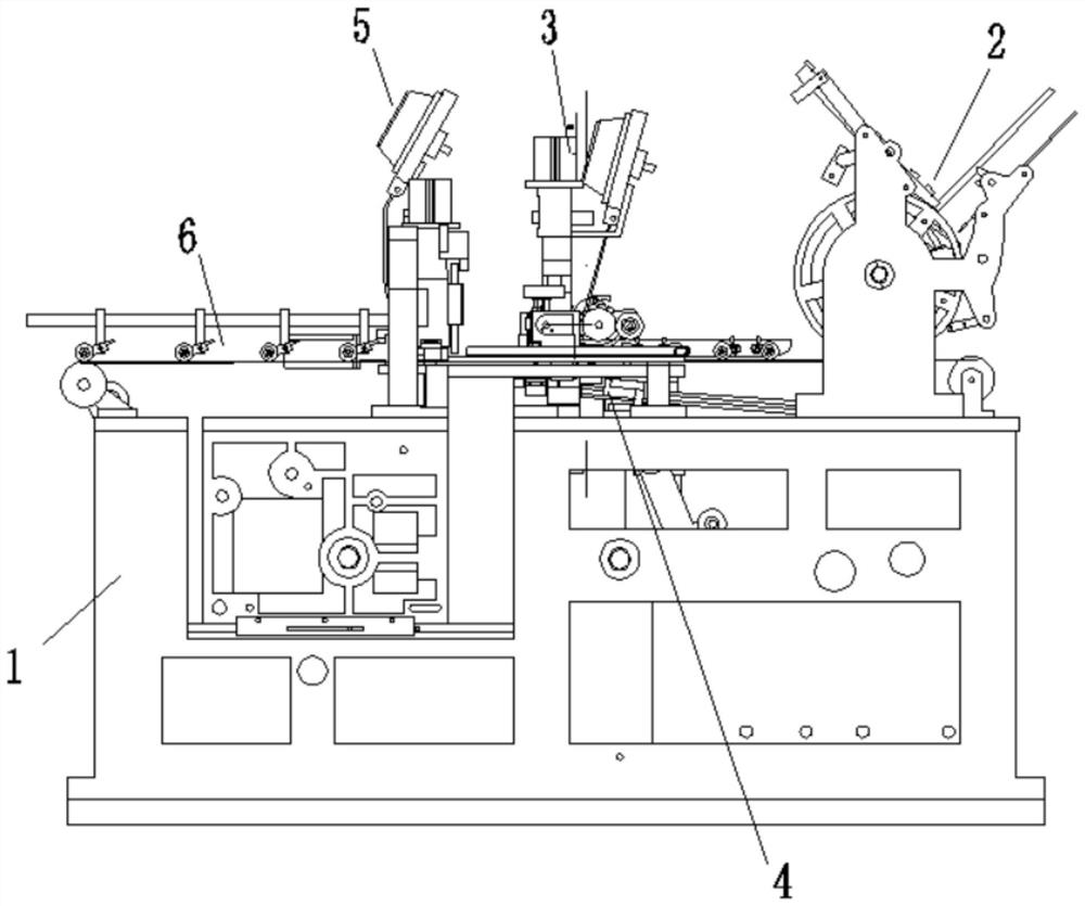
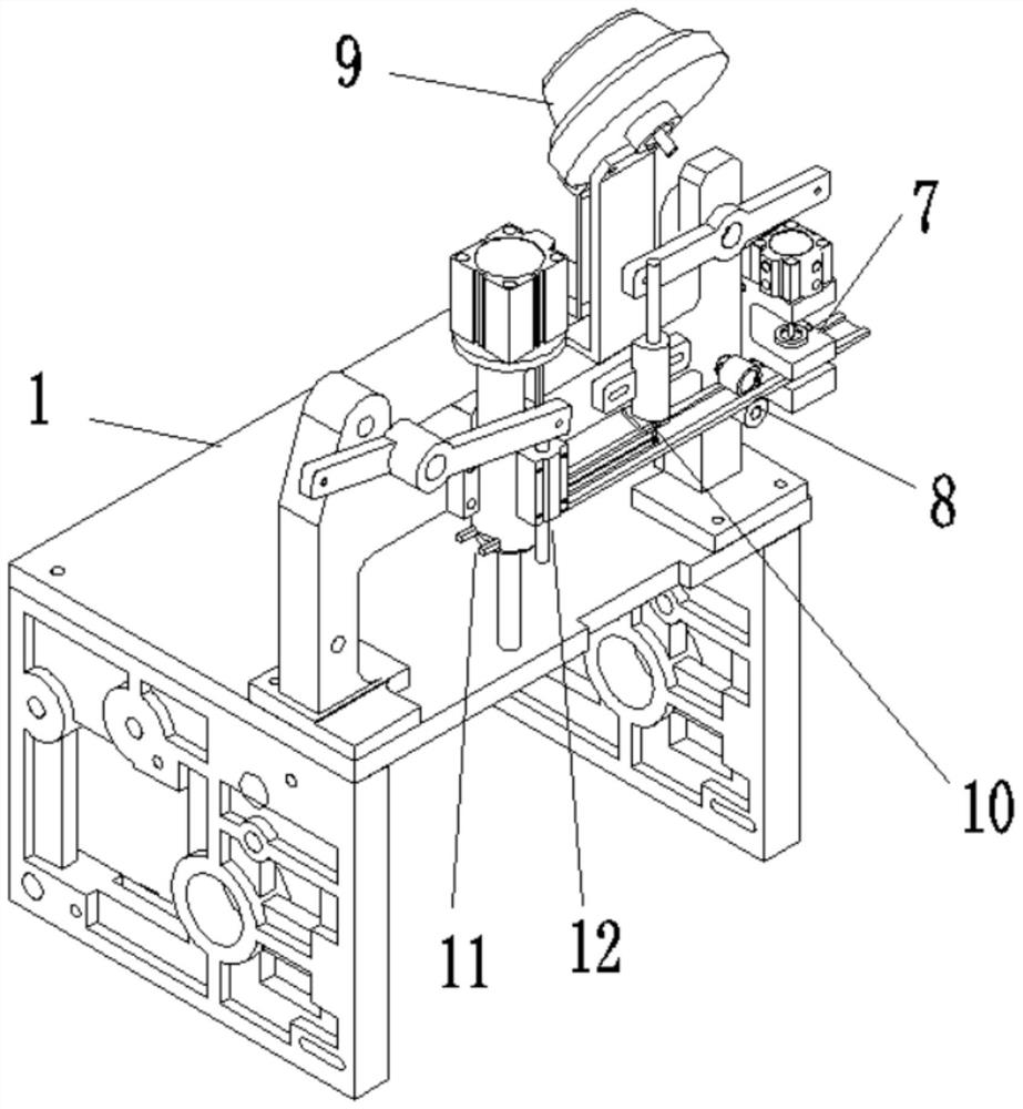
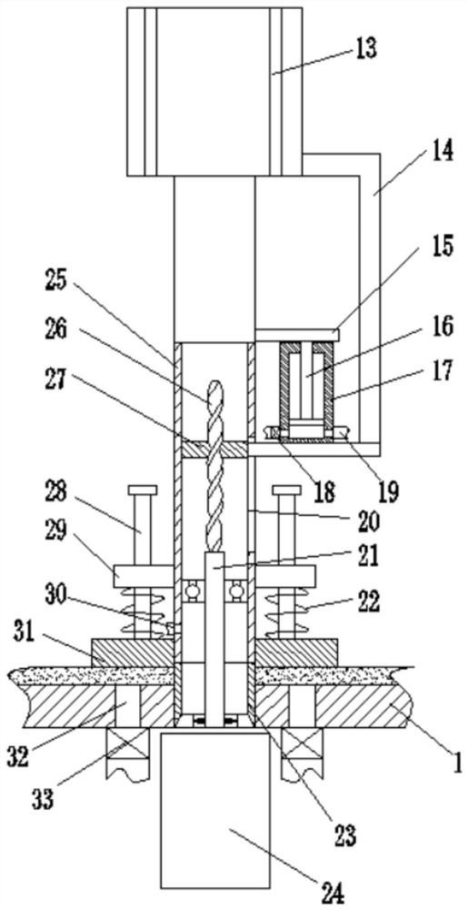
[0022] see Figure 1 to Figure 5 , the present invention provides a technical solution: an integrated envelope eye button binding machine, including a frame 1, on which an envelope feeding device 2, an envelope tongue mouth pressing device 3, a rope threading device 4, The crimping device 5 at the front of the envelope and the output device 6 for finished products, the threading device 4 is located under the crimping device 3 at the tongue of the envelope, the crim...


PUM


Abstract

The invention relates to the field of envelope binding equipment, in particular to an integrated envelope eyelet binding machine. The integrated envelope eyelet binding machine comprises a rack, an envelope feeding device, an envelope tongue opening position pressing and buckling device, a rope threading device, an envelope front face position pressing and buckling device and a finished product output device are arranged on the rack in sequence, the rope threading device is located below the envelope tongue opening position pressing and buckling device, the envelope tongue opening position pressing and buckling device and the envelope front face position pressing and buckling device are same in structure, the envelope front face position pressing and buckling device comprises a punching mechanism, a feeding roller, an inserting hole device, a pressing and buckling device and an air suction device which are mounted on the rack in sequence, according to the integrated envelope eyelet binding machine, punching, rivet putting and envelope nailing integration of a strip blank material can be achieved, error accumulation caused by in-advance punching can be avoided, the nailing error canbe prevented, work efficiency is improved, through a punching mechanism, the strip blank is punched, punching precision is improved, it is ensured that the hole inner wall is free of burrs, failuresof the envelope eyelet binding machine are avoided, and the binding quality of envelopes can be improved.

Description

technical field [0001] The invention relates to the field of envelope binding equipment, in particular to an integrated envelope eye button binding machine. Background technique [0002] In the existing envelope binding process, it is necessary to punch holes in the strip-shaped blank material for making eye buttons in advance, then put the rivets into the punched holes, and then press the rivets and strips together to buckle the envelope. In fact, this will gradually accumulate the positioning errors between the rivet placing station and the strip-shaped blank for punching holes, which will easily lead to large nailing errors, resulting in failure of the envelope eye button binding, reducing the binding quality of the envelope, and requiring multiple times. Calibrating the punching mechanism is time-consuming and labor-intensive, which reduces work efficiency. When punching strip-shaped blanks, the waste will easily block the puncher, and the inner wall of the punching hole...

Claims


Application Information

Patent Timeline
IPC IPC(8): B42B5/02
CPCB42B5/02
Inventor 陈明华
Owner 瑞安市方大信封机械有限公司
Why Eureka
Try Eureka