
Special water drainage pipeline used for building construction and capable of realizing automatic unclogging in case of clogging

A technology for construction engineering and drainage pipelines, applied in the field of drainage pipelines, which can solve the problems of inability to control the movement of blockages through its own components, the inability of floating objects to rise, and the inability to automatically dredge by force.

Inactive Publication Date: 2020-10-16
任恒学
View PDF1 Cites 3 Cited by
  • Summary
  • Abstract
  • Description
  • Claims
  • Application Information

AI Technical Summary

Problems solved by technology

[0005] In order to solve the above-mentioned technical problems, the present invention provides a special drainage pipe that can be automatically dredged when it is blocked based on construction engineering, so as to solve the problem of water generation when the existing drainage pipe is in use and cannot be conveniently discharged. The vortex cannot accelerate the flow of water to drive the flow of debris in the water, and it cannot prevent the floating objects from rising when the pipeline is initially blocked. Moreover, when the existing drainage pipeline is in use, if it is clogged, it usually requires professionals to clear it. , unable to dredge automatically under force, and unable to control the blockage to move through its own components

Method used


Image

  • Special water drainage pipeline used for building construction and capable of realizing automatic unclogging in case of clogging
  • Special water drainage pipeline used for building construction and capable of realizing automatic unclogging in case of clogging
  • Special water drainage pipeline used for building construction and capable of realizing automatic unclogging in case of clogging

Examples


Embodiment

[0035] as attached figure 1 to attach Figure 9 Shown:

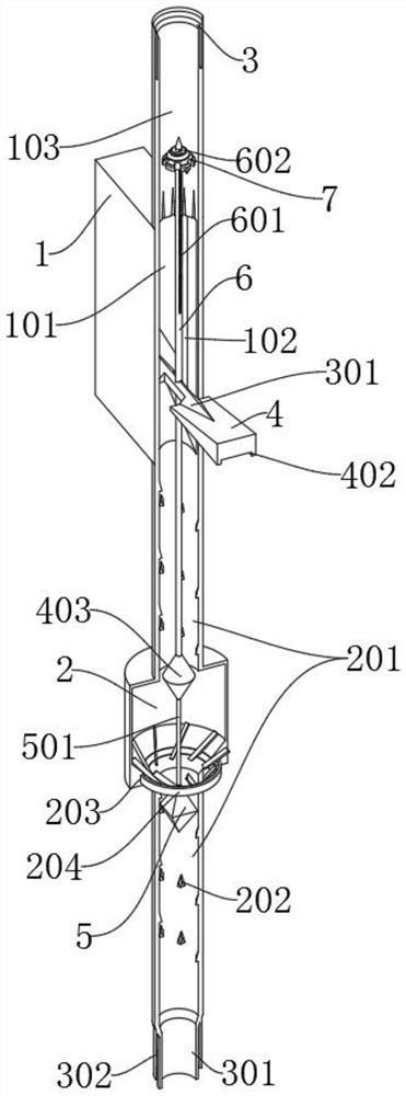
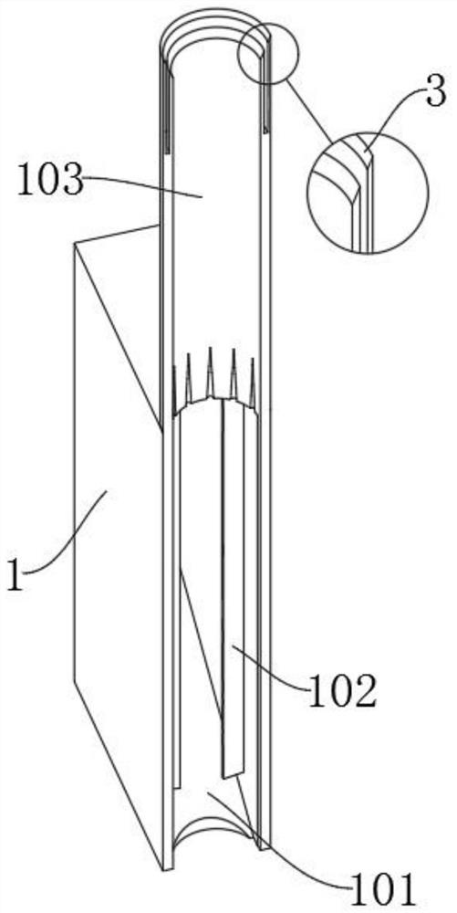
[0036] The invention provides a special drainage pipe that can be automatically dredged when blocked based on construction engineering, including a main body 1, a bottom part 2, a connection port 3, a force-bearing part 4, a pull block 5, a push rod 6 and an auxiliary block 7; the main body 1 is a rectangular structure, and the upper and lower ends of the main body 1 are provided with a circular connection hole in the middle; the connection port 3 is arranged at the top of the top pipe 103; And the outer bottom of the force rod 501 is connected to the inner bottom of the pull groove 404 through a spring; the push rod 6 is inserted into the main body 1 and the inside of the top pipe 103, and the bottom of the push rod 6 is fixedly connected to the connector 401 The middle position of the top end is connected; the auxiliary block 7 is inside the top pipe 103, and the sliding slot 701 of the auxiliary block 7 is embedded ...


PUM


Abstract

The invention provides a special water drainage pipeline used for building construction and capable of realizing automatic unclogging in case of clogging, and relates to the technical field of water drainage pipelines. The special water drainage pipeline aims to solve the problem that existing drainage pipelines in application fail to conveniently generate vortexes of water during the process of water drainage, fail to drive impurities in the water to flow by accelerating flowing of the water, and fail to avoid floating objects to rise when the pipelines are initially clogged. The special water drainage pipeline comprises a main body the main body is of a rectangular structure; circular connecting holes are formed in the central positions at both the upper end and the lower end of the mainbody; a connecting port is formed in the top of a top pipe; and a stressed rod at the top of a pull block is installed inside a pull groove in an embedded mode. A bottom member is used for being arranged at the bottom of the special water drainage pipeline, so when the special water drainage pipeline is in application, sewage enters the inside of the bottom member, the water can be in complete contact with a rotating member; and therefore, an inclined plate of the rotating member under stress can support the rotation, the rotating member can rotate inside a rotation groove and the inclined plate can stir falling water.

Description

technical field [0001] The invention belongs to the technical field of drainage pipes, and more specifically relates to a special drainage pipe that can be automatically dredged when blocked based on construction engineering. Background technique [0002] Drainage pipes refer to the system composed of pipes and channels for collecting and discharging sewage, waste water and rainwater and their ancillary facilities. Regardless of whether they are built on streets or anywhere else, as long as they are used for drainage, they should be counted as drainage pipes. [0003] For example, the application number: CN201810608361.2 relates to a drainage pipe, including a main body of the pipe, an opening at the top of the main body of the pipe, and two partitions are arranged in the middle of the main body of the pipe. The main body is integrally connected, and the two partitions separate the drainage channel in the middle of the main body of the pipe. The bottom of the pipe forms a bo...

Claims


Application Information

Patent Timeline
IPC IPC(8): E03C1/12E03C1/30E03F7/00
CPCE03C1/12E03C1/30E03C2001/1206E03F7/00
Inventor 任恒学
Owner 任恒学
Learn More